Making TEM cell for EMC measurements
What is TEM cell?
I love the simplest explanation for a TEM cell that I’ve heard:
It’s a really weird coaxial cable
TEM (Transverse electromagnetic) cell is a device that generates electromagnetic waves from 0 Hz up to few hundred MHz in an area between shielding plates and center plate called septum. This chamber is widely used for testing small electronic devices for radio noise emissions and immunity (EMC/EMI).
EMC/EMI measurements in anechoic chamber
The best way to do EMC/EMI measurements is to use anechoic chamber and calibrated EMC antenna. Chamber, antennas and other equipment is really expensive and only certification labs can afford it. EMC certification measurement in certification labs costs up to 1000USD. That’s still quite expensive for startups and hobbyists. Especially if your device development is still in progress and you have to make multiple measurements to fix all EMC/EMI issues in your device.

The reason for big anechoic chamber is that you have to measure device in a far field region (radio waves from/to device have to be planar). In a chamber you can achieve far field by placing antenna far enough from device under test and you need a shielded chamber to isolate your measurement from outside radio noise.
Why is the TEM cell shape like this?

Disclaimer: My explanation is really unscientific to make it more understandable for readers without any radio background. I recommend you to read articles in the Sources chapter to get a scientific explanation.
As I mentioned in a previous chapter, the goal is to achieve planar electromagnetic waves. When you use antenna you have to place your device far enough from the antenna to achieve such waves. But what if I told you that there is a way to generate planar waves directly without antenna…
Imagine a coaxial cable. Inside a coaxial cable is an electromagnetic field also kind of planar. We can make a coaxial cable using air as a dielectric insulator, and we can make the coaxial cable really huge. So huge that we can fit our device inside a coaxial cable (somewhere between center conductor and shielding). To make this huge coaxial cable bit more practical we can make symmetrical holes from sides and to make electromagnetic field more planar we can make its shield and center conductor as plates. That’s how TEM cell is made. It’s a really weird rectangular air coaxial cable.
Sources
M.L. Crawford, “Generation of standard electromagnetic fields using TEM transmission cells”
https://ieeexplore.ieee.org/document/4090850
Sandeep M. Satav, Vivek Agarwal. Do-it-Yourself Fabrication of an Open TEM Cell for EMC Pre-compliance
http://eagle.chaosproject.com/sandbox/acstrial/newsletters/summer08/pp2.pdf
Cemil Yıldız, Gülsima Demirel, Fatma Çalışkan. Designing Transverse Electromagnetic (TEM) Cell
http://www.emcturkiye.org/papers/Session7_Talk4.pdf
The Current Source YouTube Channel. DIY TEM Cell for EMC Pre-Compliance Testing
https://www.youtube.com/watch?v=muJ5nH4bqQ8
Why I designed it and build it
I develop and test a lot of hardware. Most of my hardware designs have to be certified for EMC/EMI compliance so It would be really helpful to have some way to do pre-compliance measurements right in my lab. I didn’t consider an anechoic chamber at all for obvious reasons. An alternative for the anechoic chamber is benchtop Faraday cage with EMC antenna. Faraday cage and EMC antennas (biconical antennas) are still quite pricey for startup or hobbyist and hard to find as second-hand equipment. After some research, I’ve found some articles about TEM and GTEM and I knew that I have to give it try and try to build my own TEM cell.

However, I wasn’t able to find any article with precise dimensions. Every time I’ve tried to put all the dimension into CAD to check if everything sums up I always found some mistakes. I end up using most dimensions for straight parts of shielding and septum from Sandeep M. Satav article. Transitions between RF connectors and straight part and structural parts are my own design.
My TEM cell design
My first cell was made of 0.5 mm copper plates for shielding and 0.25 mm FR4 for septum. After some measurements I found out that this design is not good and I end up redesigning the septum. I don’t think that the issue was septum material (FR4 is very common choice for TEM cell constructions for its rigidity and availability) but the shape of the septum. I’ve decided to post information about this faulty version to demonstrate results when design goes wrong.

Second version of cell was made from 0.5 mm copper plates only (because I have no FR4 left) and the shape of septum was tuned. Performance of full copper version seems to be fine for a homemade TEM cell.
Fusion360 model and drawings
Model – https://a360.co/2XTrcFQ
Assembly Drawing – https://a360.co/3hhxW81
Septum Drawing – https://a360.co/2MN9jC6
Shielding Drawing – https://a360.co/2YEcYIj
Assembly and operation volume
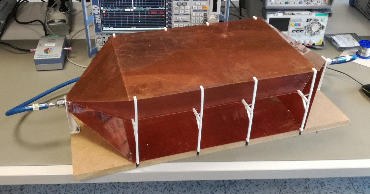
Outer dimensions of TEM cell are 723 x 300 x 181 mm. Operation volume for TEM cell is considered as a third of straight section volume which is roughly 50 x 50 x 30 mm.


TEM cell is made of two shielding plates, septum plate, N-female connectors, 8pcs of M3x10 screws and M3 nuts, 3D printed structural supports and side stands, 4pcs M4x20 screws, nuts and washers and MDF board.
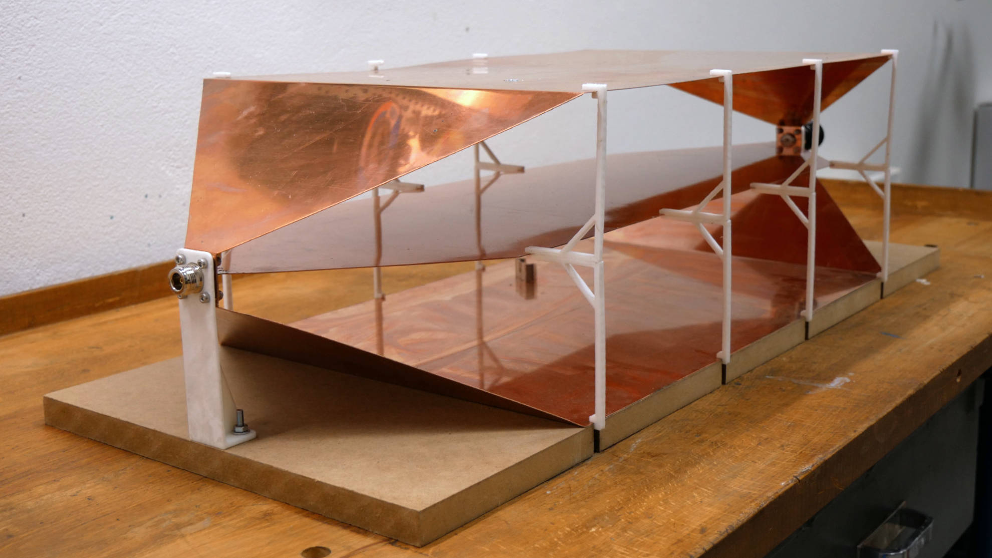
Shielding plates are held together by screws for N-female connector and the horn shape is supported by 3D printed connector stands. Top shielding and septum is supported by eight 3D printed side stands. Side stands are made of two same parts glued together (My 3D printer is too small to print such a part as one piece).

Septum is held only by side stands and solder joints to N-female connectors center pins. I had to use some boxes and PCBs to support septum and top shield in a precise position during assembly and soldering.

Copper shielding
Shielding is made of two same plates. These plates are made of 0.5 mm copper. I recommend drilling holes for N-female connector first and then cutting plates to final size. Copper is a very soft metal and drilling will most likely cause bending of a shielding plate (I did this mistake by myself and I almost destroyed whole plate when I was drilling a 25 mm hole…)


MDF base board
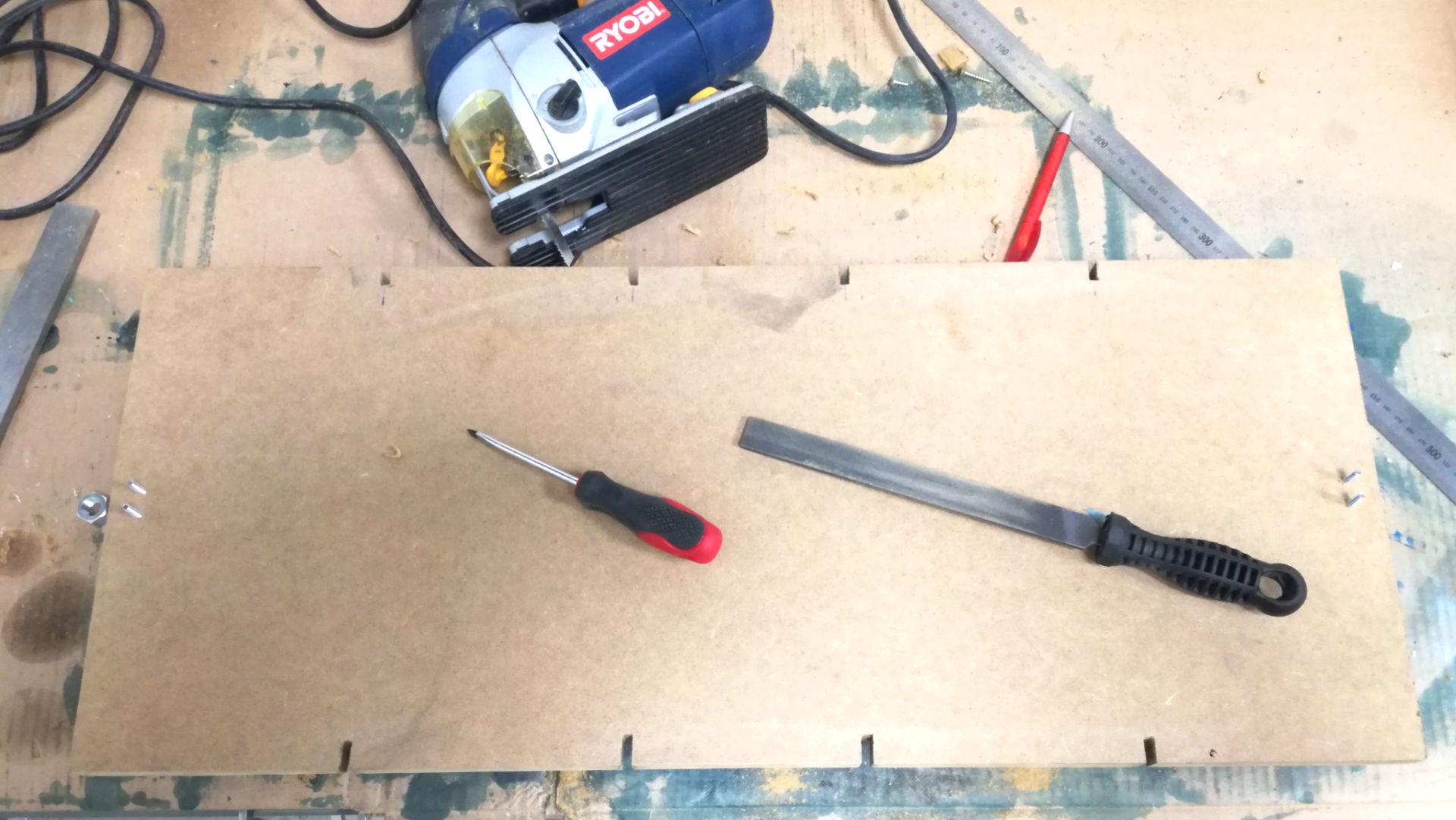
Size of the MDF board is same as TEM cell dimension – 723 x 300 mm. Thickness is 18 mm but you can use thinner MDF or plywood. I cut slots for 3D side stands and drilled 5 mm holes for connector stand screws.
3D printed connector stand
Connector stand supports N-female connector and shielding plates against base desk and ensures correct cell dimensions and angles of bottom shielding plate. This part is made of ABS on FDM 3D printer.

STL model exported from Fusion360:

3D printed side stand
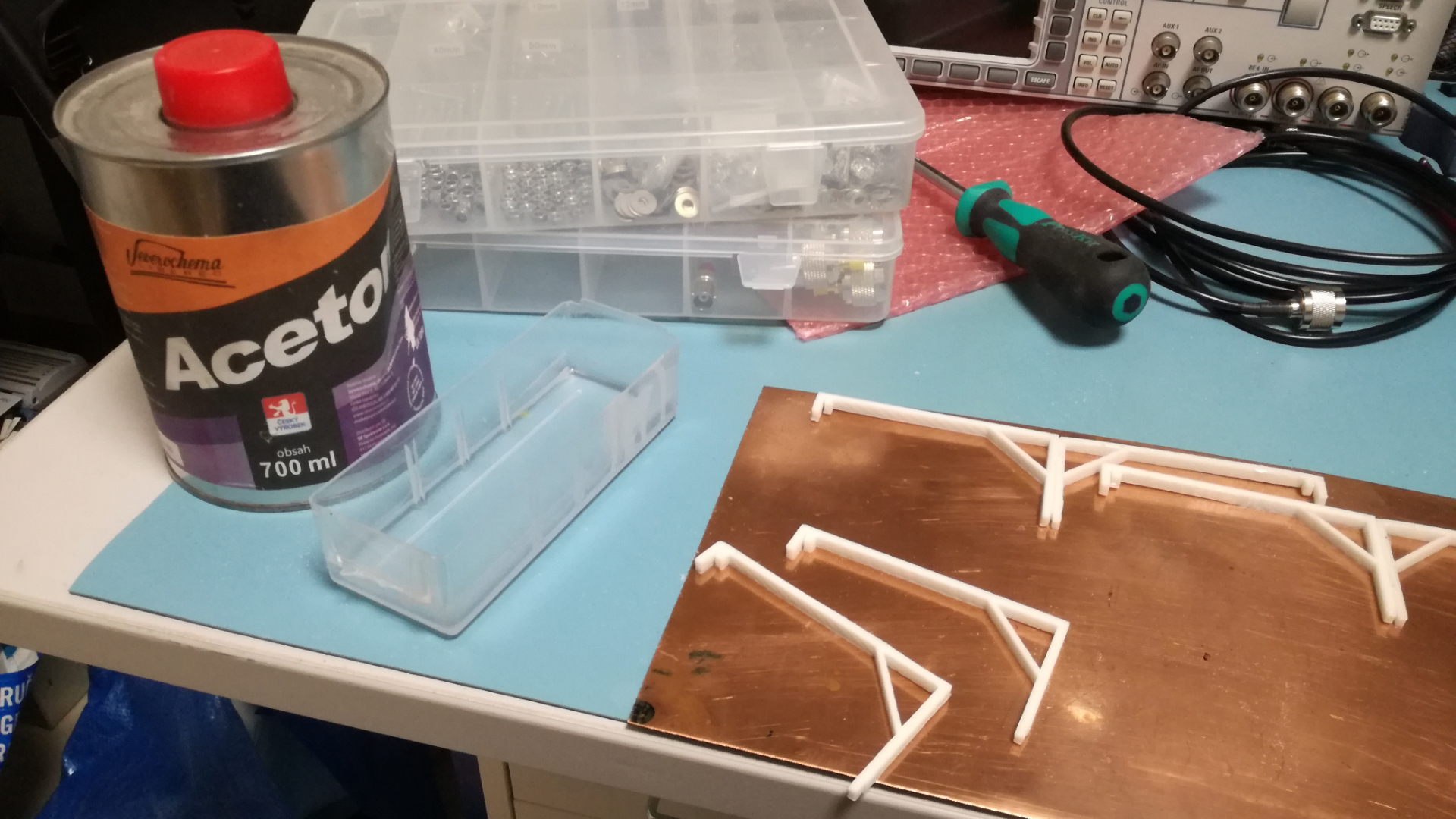
Copper is very soft material and it is necessary to support cell structure. Complete stand is made of two 3D printer ABS parts glued together with acetone thinner.

STL model exported from Fusion360:

FR4 septum
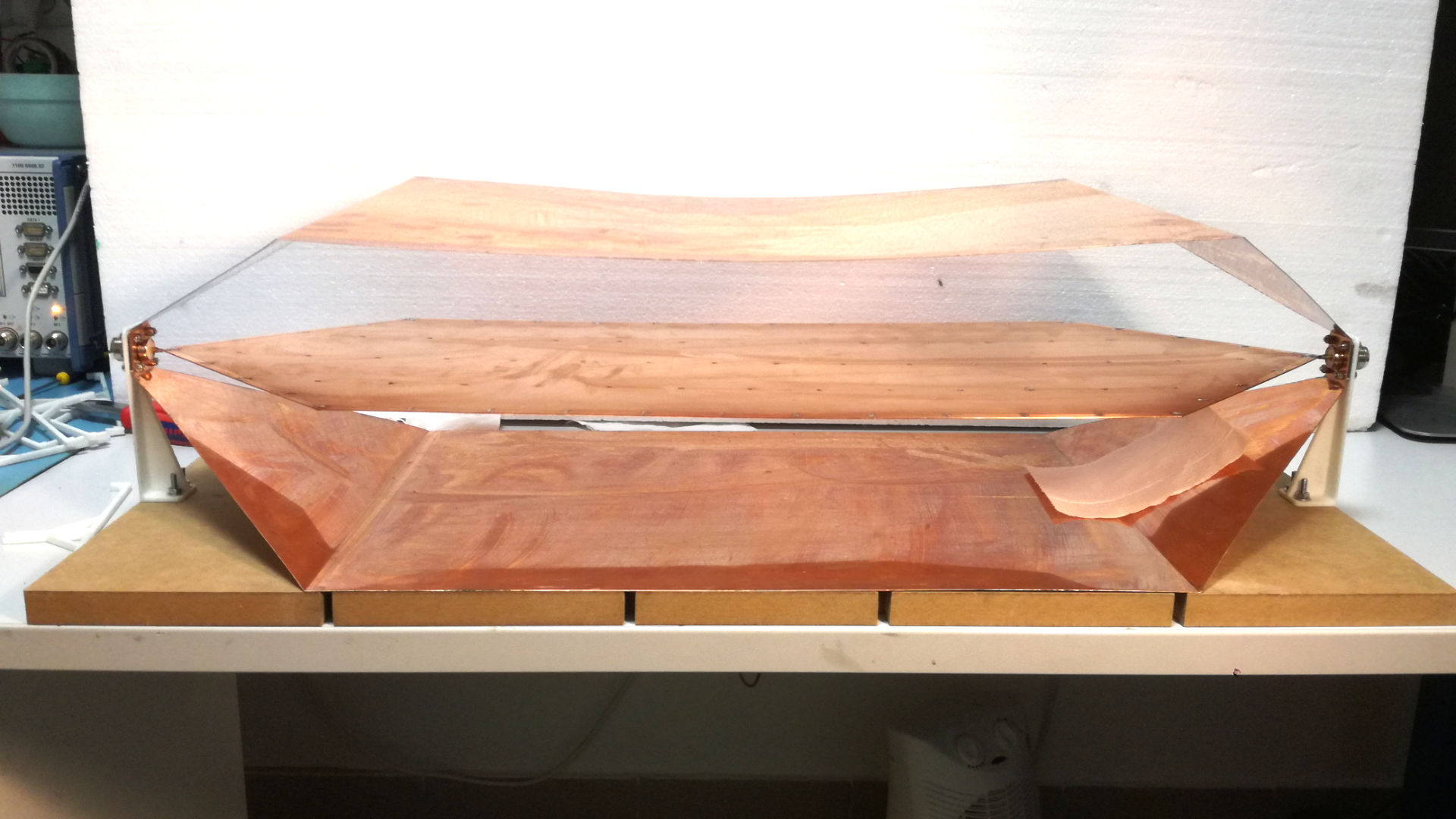
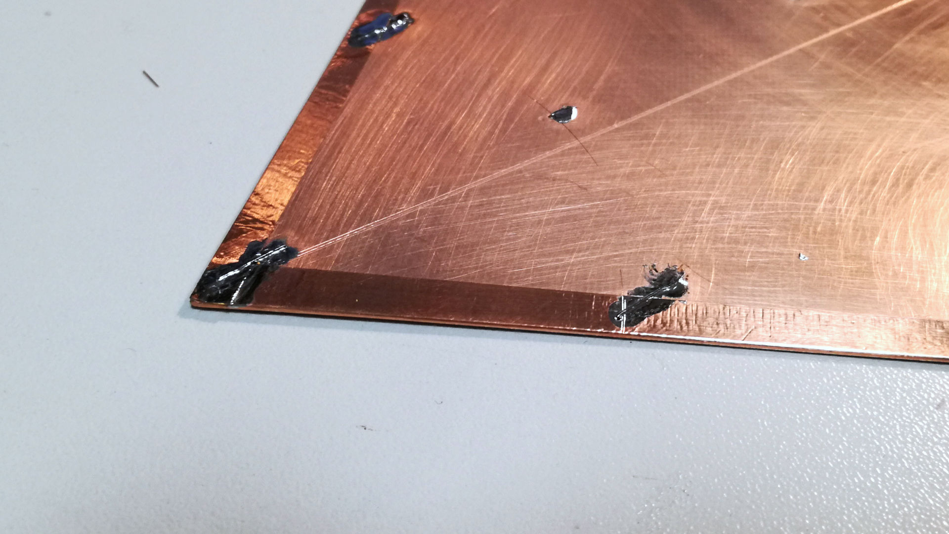
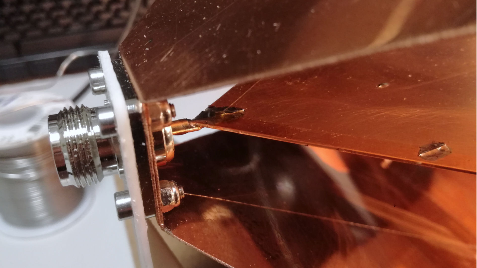
The shape of my first septum was incorrect but I wanted to write about it in my article to demonstrate bad design choices. The reason behind this design is that I was confused about the shape of septum published in the article by Sandeep M. Satav. Drawings and pictures in his article are in low-resolution and It is not possible to see how the septum should be soldered to the RF connectors. So, The main issue with my first septum is RF connector section. Septum end was reaching only the tip of the central conductor of the RF connector. The correct solution (Copper septum in next chapter) is a smooth transition right from the edge of the N-female connector body.
FR4 septum is made of 0.25 mm thick double-sided FR4. All edges are covered with self-adhesive copper foil and septum is drilled with a grid of holes and all of these holes were soldered with a thin copper wire. I made this modification because I thought that it will have effect on a performance on high frequencies. Actual effects of this modification are questionable most likely unnecessary.


Copper septum
The second version of my TEM cell septum is made of 0.5 mm copper plate. The main difference from the first version is cut-out for N-female connector pin. This cut-out allows septum to be placed close to the edge of the connector and it massively improves impedance properties.


TEM cell measurements and tests
FR4 septum version measurements has been made on Rohde&Schwarz ZVA40 vector network analyzer. Then I modified my TEM cell to the second version with full copper version but I’ve lost access to ZVA40 at the same time. Right now I own only NanoVNA V2, so I’ve made the rest of the measurements with NanoVNA. I also did RF load measurement to be able to directly compare results from lab-grade VNA with hobby-grade NanoVNA.


RF load
I was using 5W 0 – 6 GHz RF load from Aliexpress for all measurements. S11 measurement was made on this load as a reference on both Rohde&Schwarz ZVA40 and NanoVNA V2.

https://www.aliexpress.com/item/32887489597.html
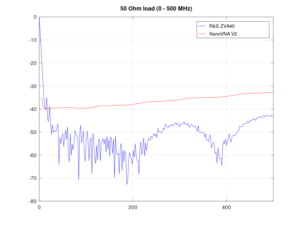

10 dB difference is caused by the low resolution and/or lower sensitivity of much cheaper NanoVNA V2. Rohde&Schwarz ZVA40 is an expensive lab-grade VNA so this difference was expected.
S-parameter measurements
Impedance measurement of the TEM cell loaded with 5W RF load


Copper septum improvement is around 2 dB in peaks. It does not sound as much but the peak at 450 MHz is now at -6 dB. Radiofrequency structures with reflections under -6 dB are usually considered as sufficiently impedance matched. It could be better but I think that it’s as good as it gets in my hobby conditions.
Two-port impedance and insertion loss measurement
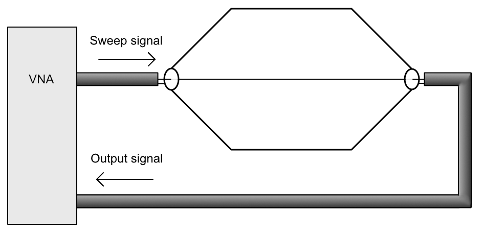
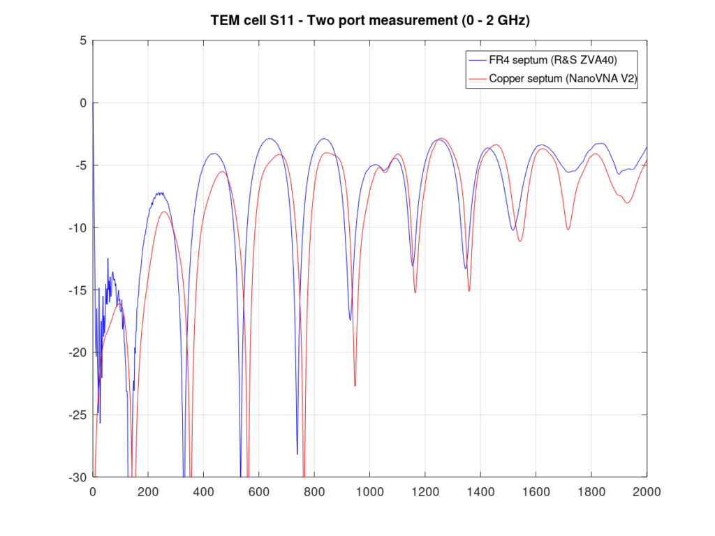


Some improvement in insertion loss is also visible.
EMC measurement for test device
I would like to demonstrate in this article brief EMC measurement. I will make an extra blog post just for the EMC pre-compliance measurement in the future. I’m using Rohde&Schwarz CMU200 in my laboratory. CMU200 is an old radio communication tester for testing devices for 3rd generation GSM networks. These testers can be found on eBay for low prices and could be used as spectral analyzers and generators in the range from 10 MHz to 2.7 GHz.


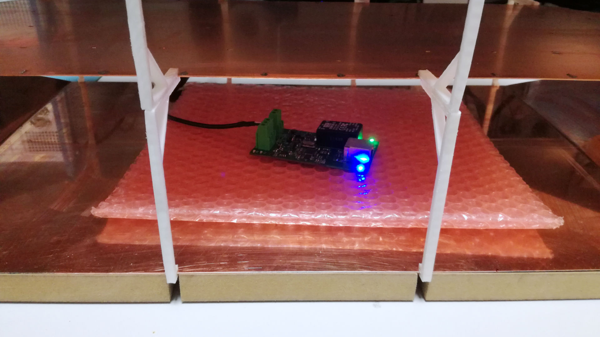

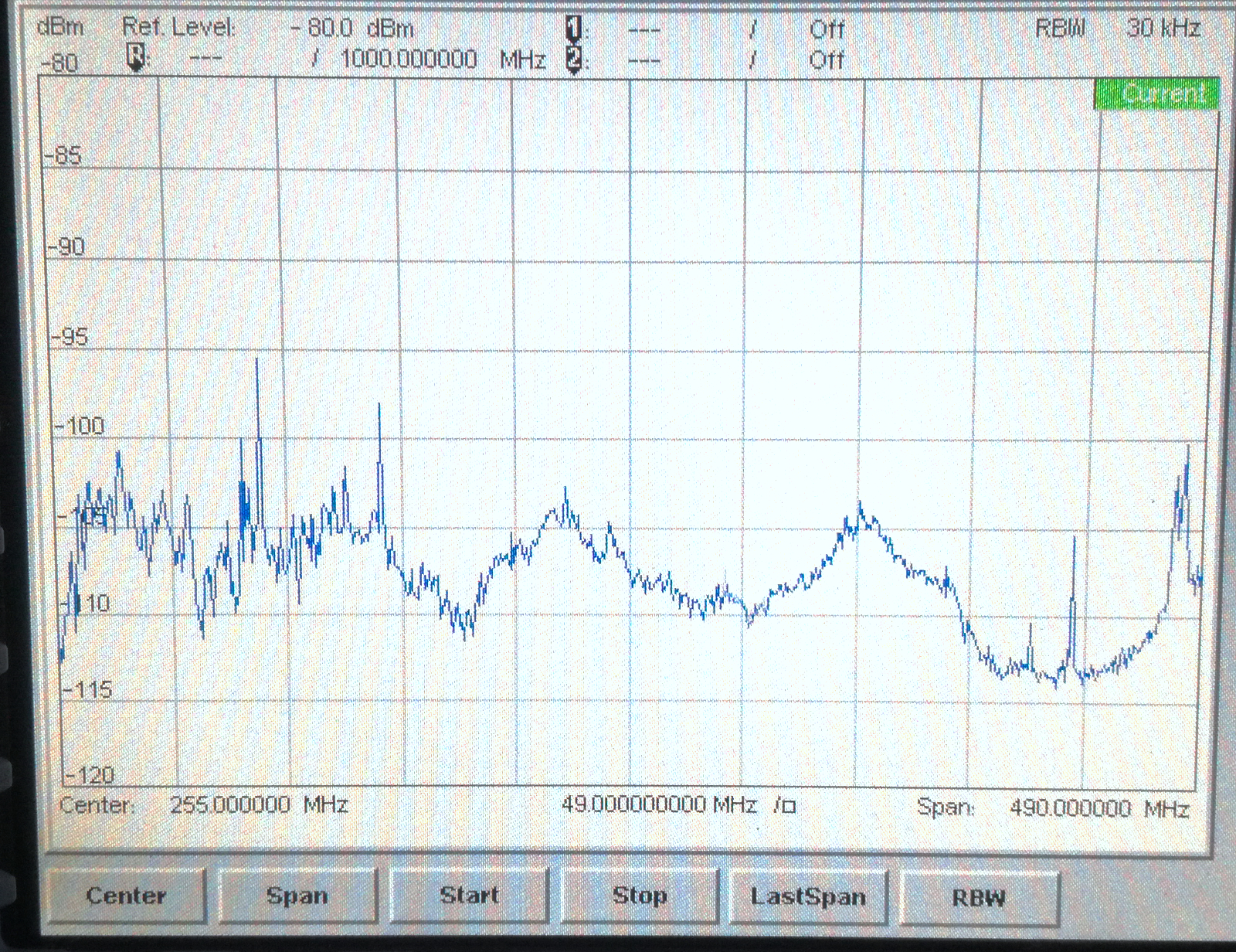
Device for my first test was probably not the best one. This device was designed according to EMC/EMI PCB design guidelines and the noise generated by the device is pretty low especially under 150 MHz where FM radios are much stronger source of signal.
Conclusion
Based on impedance matching measurements is my TEM cell useful for measurements and field generation up to 550MHz. Sensitivity for basic EMC measurements seems to be fine as well however, open-cell design does not offer any shielding against outside noise such as FM radios, nearby ISM devices, and mobile phone networks. I think that my TEM cell is useful only for highly noisy devices that will generate signals stronger than outside noise or for generating radio fields for EMI test.
My future plans regarding pre-compliance EMC are:
- Open TEM cell shielding performance measurement
- Installation of shielding my laboratory using conductive curtain and eliminating all noise sources in my laboratory (noisy LED lights)
- Comparison of a TEM cell EMC pre-compliance measurement with results from EMC certification laboratory on the same device
- Closed TEM cell design and manufacturing
- GTEM cell design and manufacturing

Hi! Great information here. I’m taking your details in addition to Satav’s construction details to make my own. Much appreciated! With that said, I think you mean female N-type connectors (not male) for the TEM cell.
You are right about the N-type connector, I will fix it. Thank you and good luck with your construction.
Very nice! What was the final cost?
Thank you! 🙂 Exact price is a kinda hard question. The material for the contruction costs few euros, I guess that cost of material was less than 50 euros in total. The price of the time that I’ve spent on manufacturing will be much higher, around 3 man-days is my estimation. And I also had to buy some tools for working with metal plates like plate bender and sheet metal nibbler (Knipex 90 55 280).