

Nissan 180SX/240SX S13 Digital Speedometer Schematics
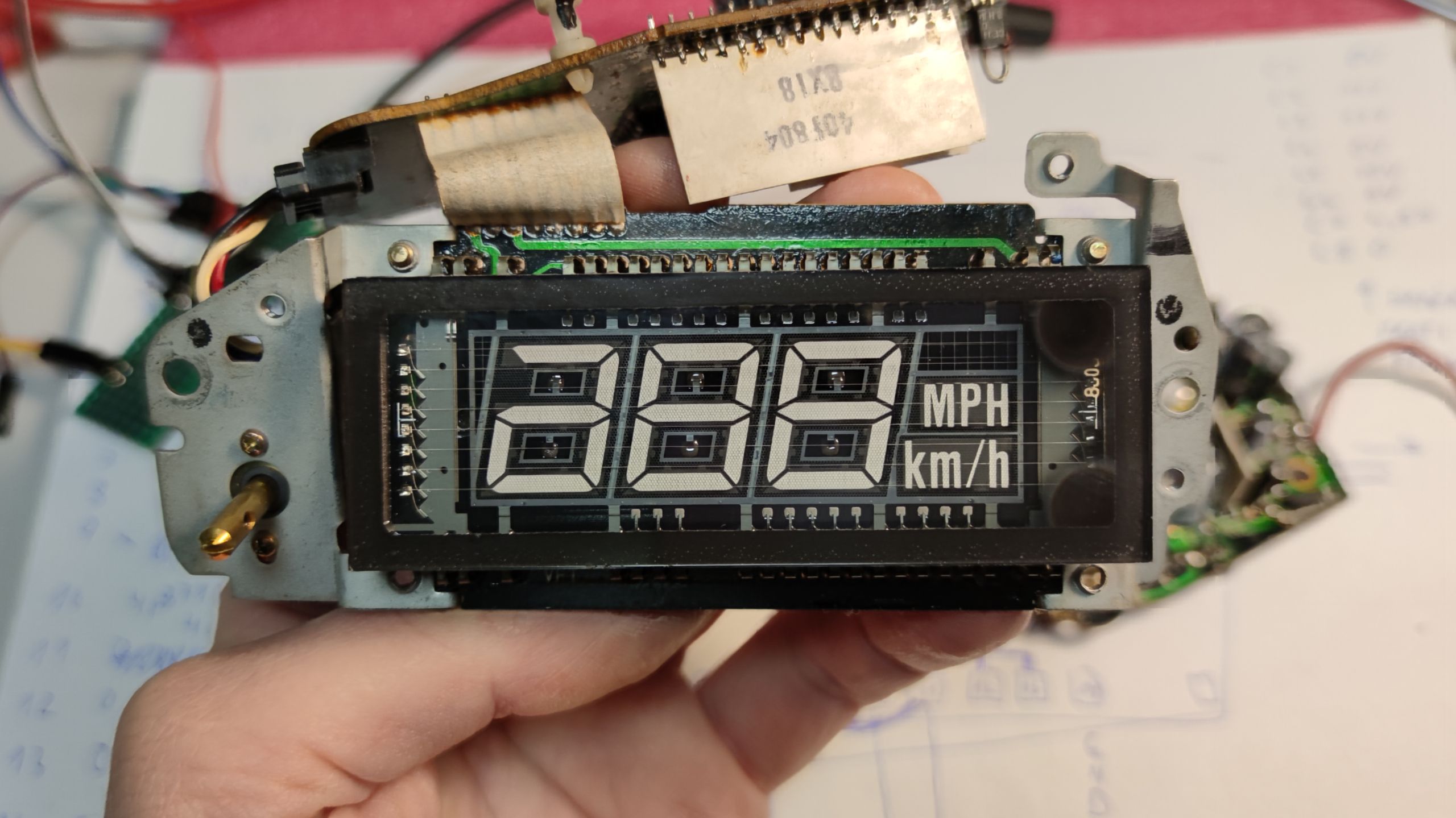
This speedometer got into my hands when my friend asked me if I could try to repair it. I’ve started with visual inspection and didn’t find any visible issue, so I started searching for some forum posts that could have some helpful information. Most of the posts that I’ve found were mentioning the replacement of capacitors and cold solder joints. I’ve replaced every single electrolytic capacitor on the board, but the speedo was still not working at all, not even showing “0 KMPH”. Due to lack of any service information, I’ve decided to reverse engineer electronics of the whole speedo to be able to further diagnose the circuit. Maybe this article will be helpful for others that want to try to repair this speedo.


Keep in mind that all these schematics were done by me without any authorization from Nissan.
That means that most likely there will be a lot of errors. If you find any, I would really appreciate it if you let me know in the comments.
The naming of the signals was also guessed by me, and if there is an “???” it means that I wasn’t really sure what name to choose for a part or for the signal. This is mostly the case for diodes that are really hard or impossible to identify due to missing marking or marking that is impossible to lock up to some specific part. All zener diodes that have voltage value specified were soldered out and measured outside the board with a voltage source and 1000 Ohm resistor in series.
Also, I wasn’t able to identify the naming of HUD signals because I didn’t get my hands on this unit.
The last issue is with photos. Most of the high quality photos were made after my attempts to repair the board. That means that most of the photos that I’ve made contains new capacitors. Schematics contains values of the original capacitors, and I post photos of original capacitors in the image gallery at the end of this article.
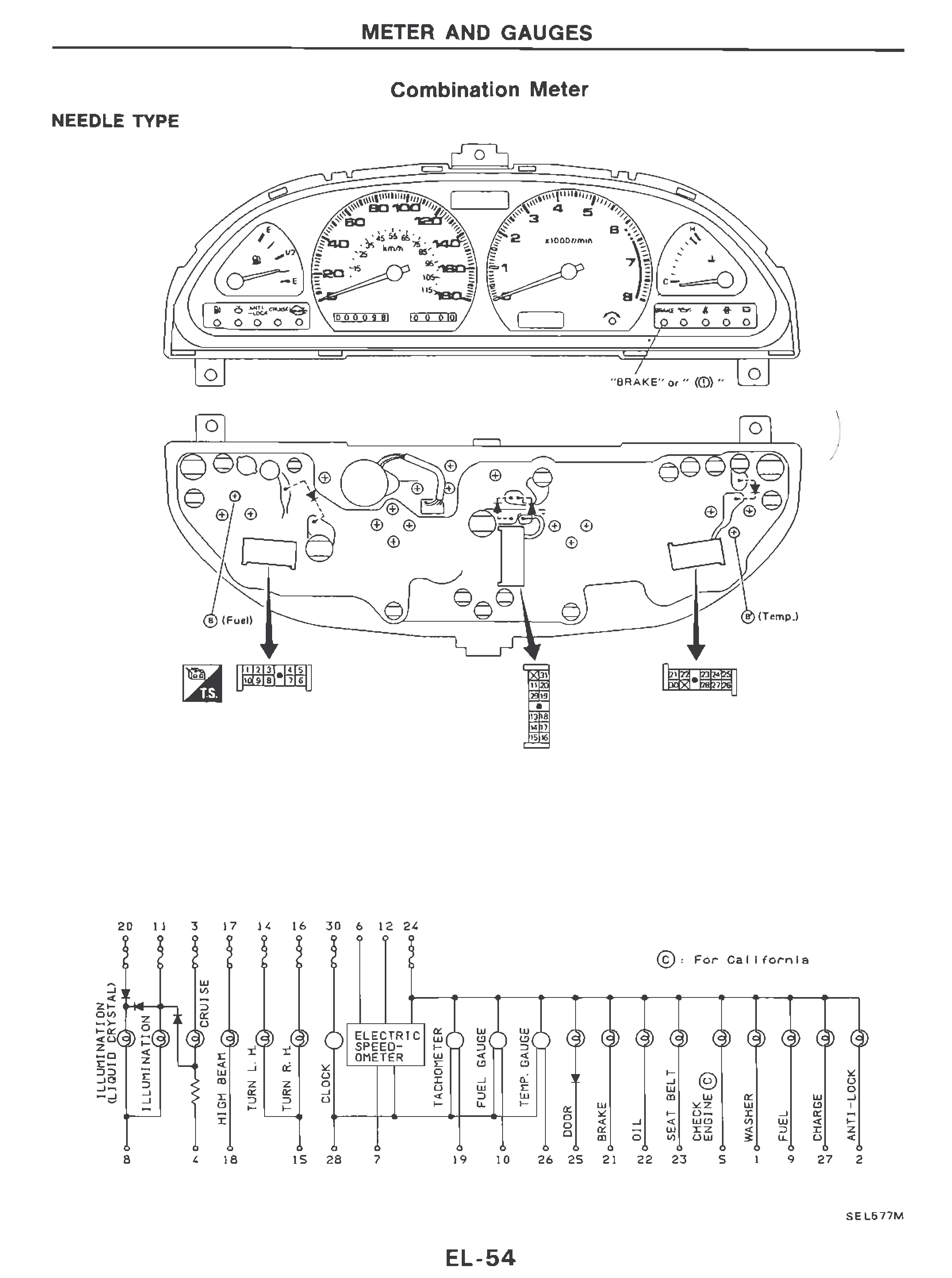
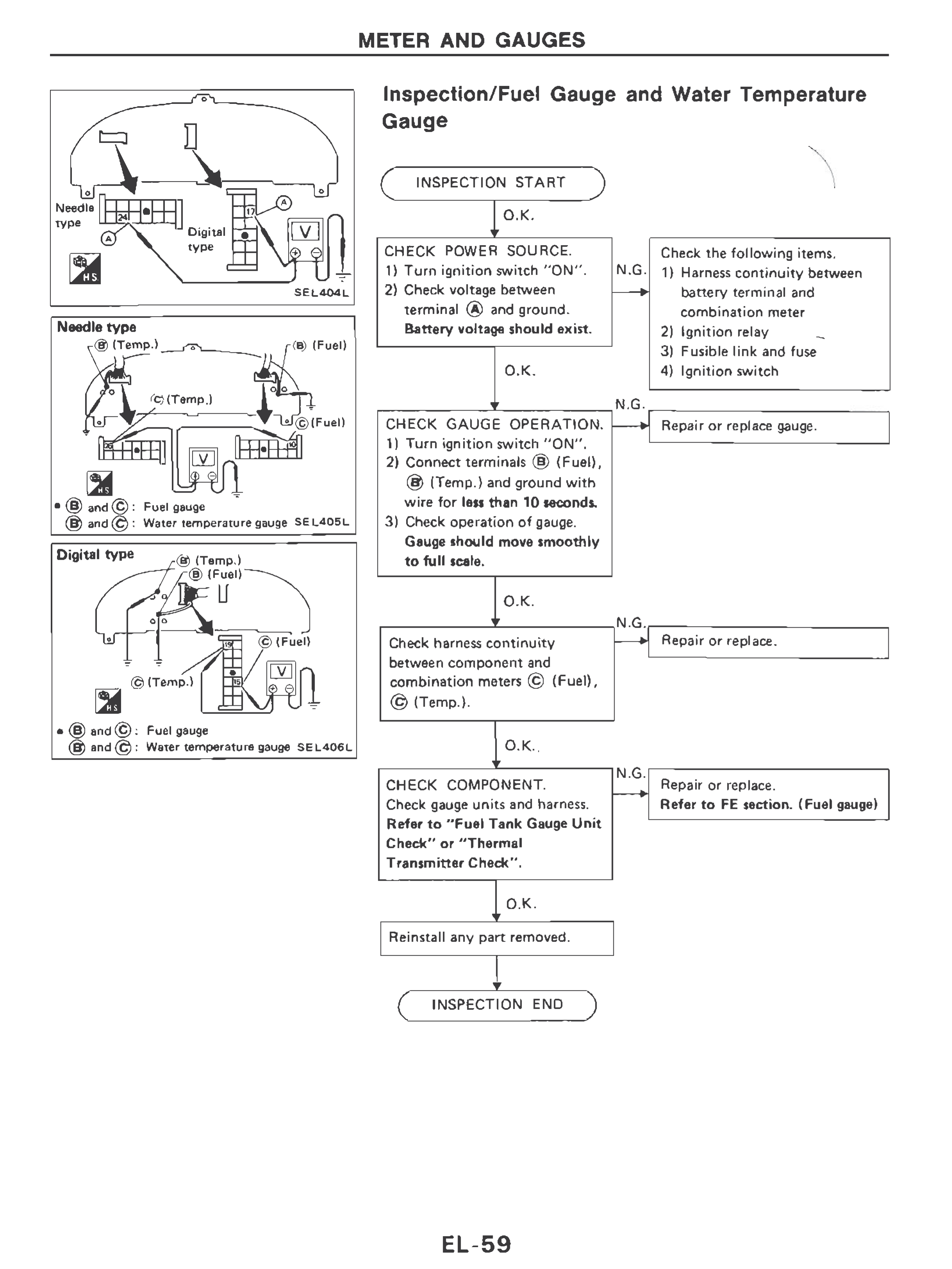
Service manual
Information related to combination meter that I’ve found in 1989 Nissan 240SX service manual.


Schematics
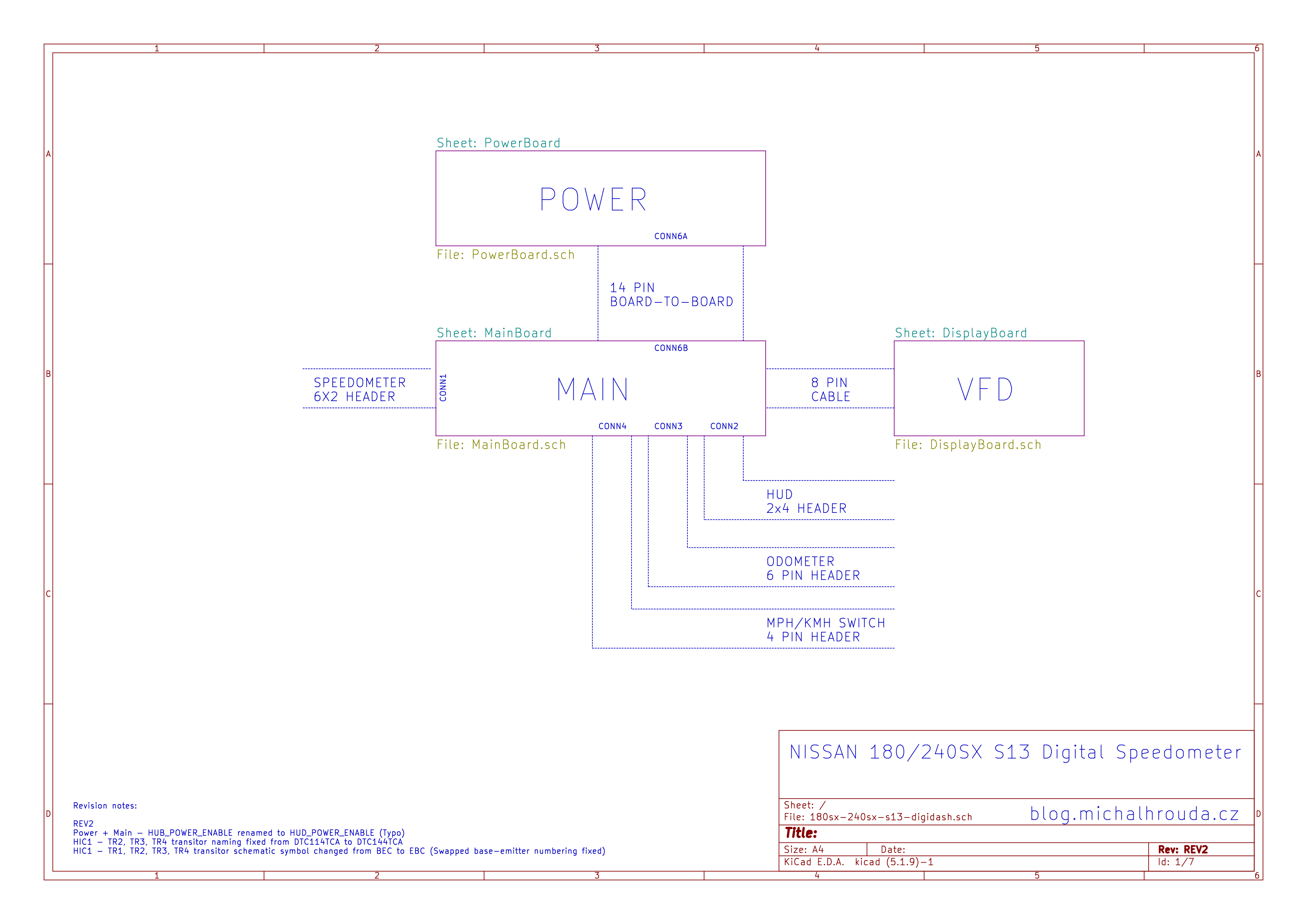
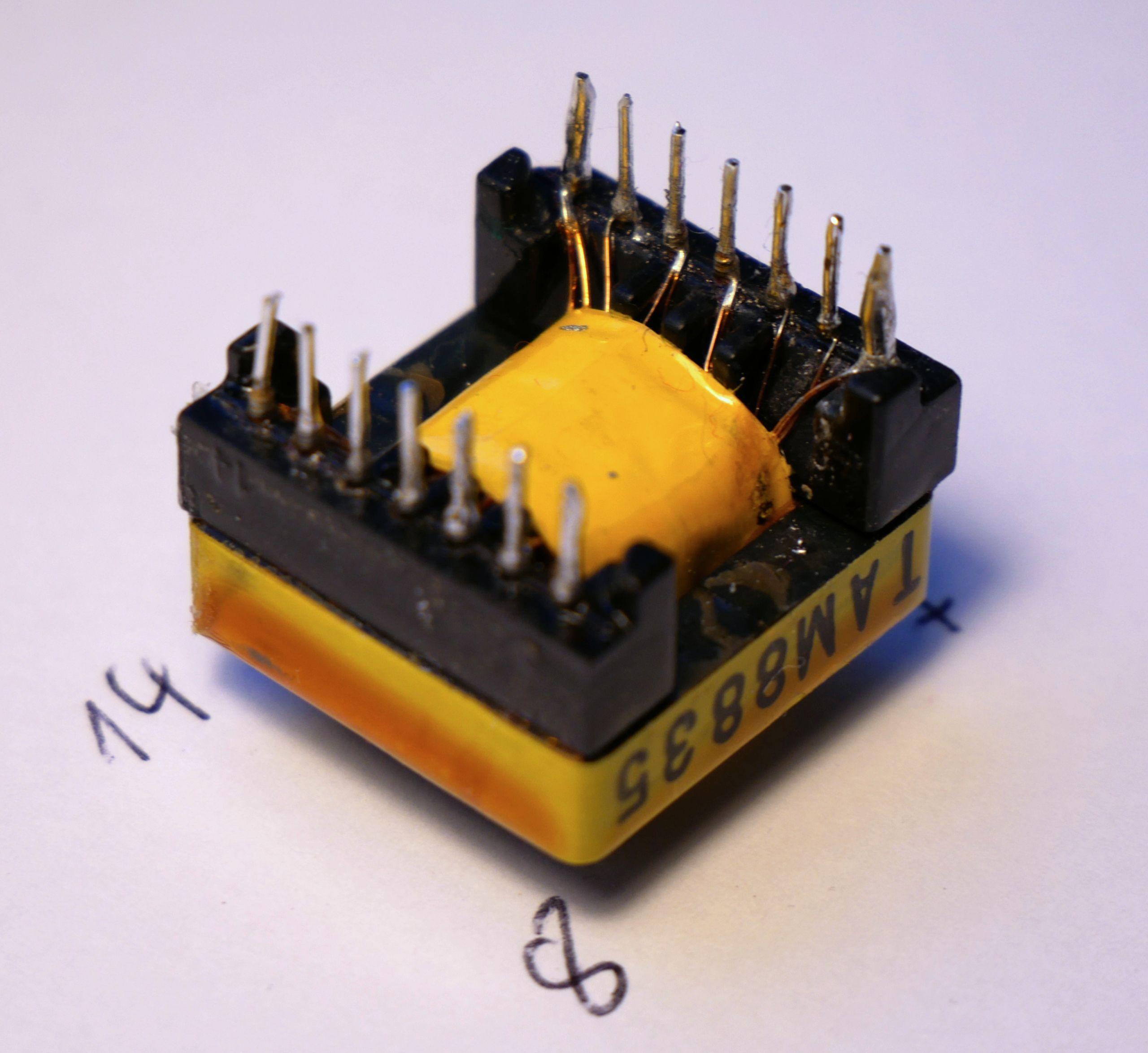
Digital speedometer is made of three separate boards. The main board provides a connection to the outside world, VFD display control and HUD control. The power supply provides +5V, +10V and current sources for speedo and HUD display filaments (cathodes).
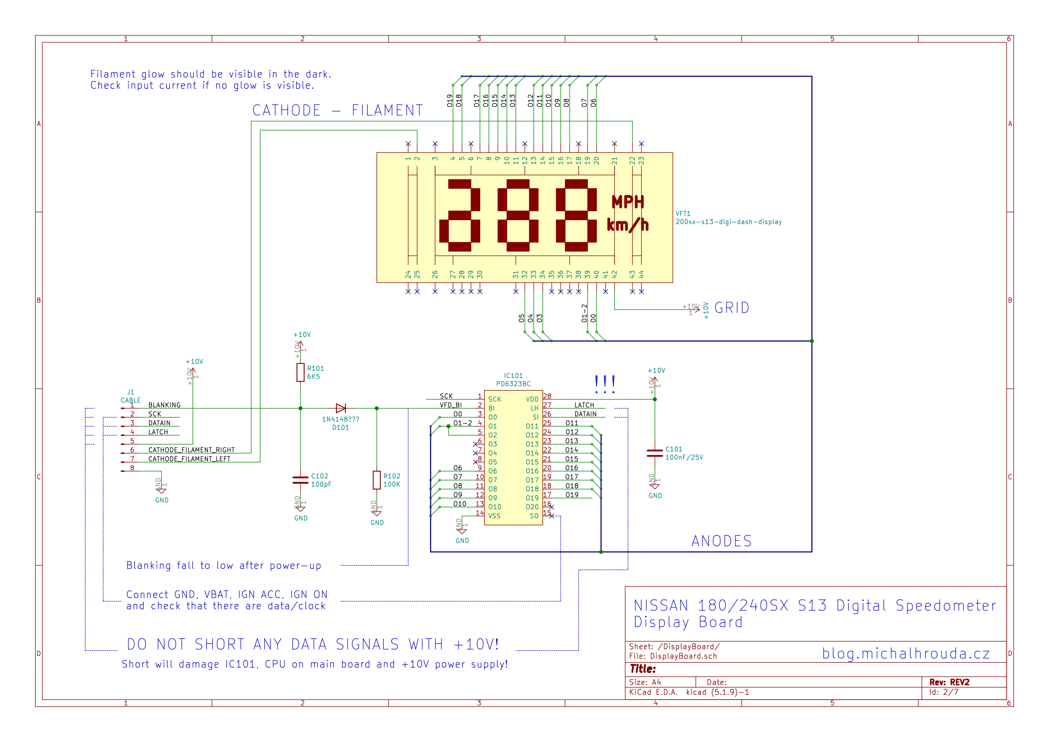
Display board
Chip on this board PD6232BC shift register with outputs for driving fluorescent vacuum displays. The chip is driven by clock, data, latch signal and blanking signal. On my board I was able to measure all control signals from the microcontroler and on the SO output of the PD6323 so the issue with my speedo was most likely related to power supply.


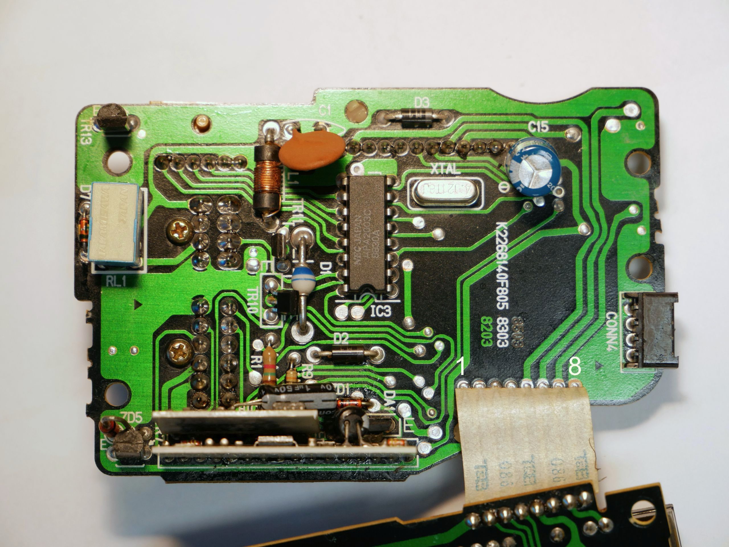
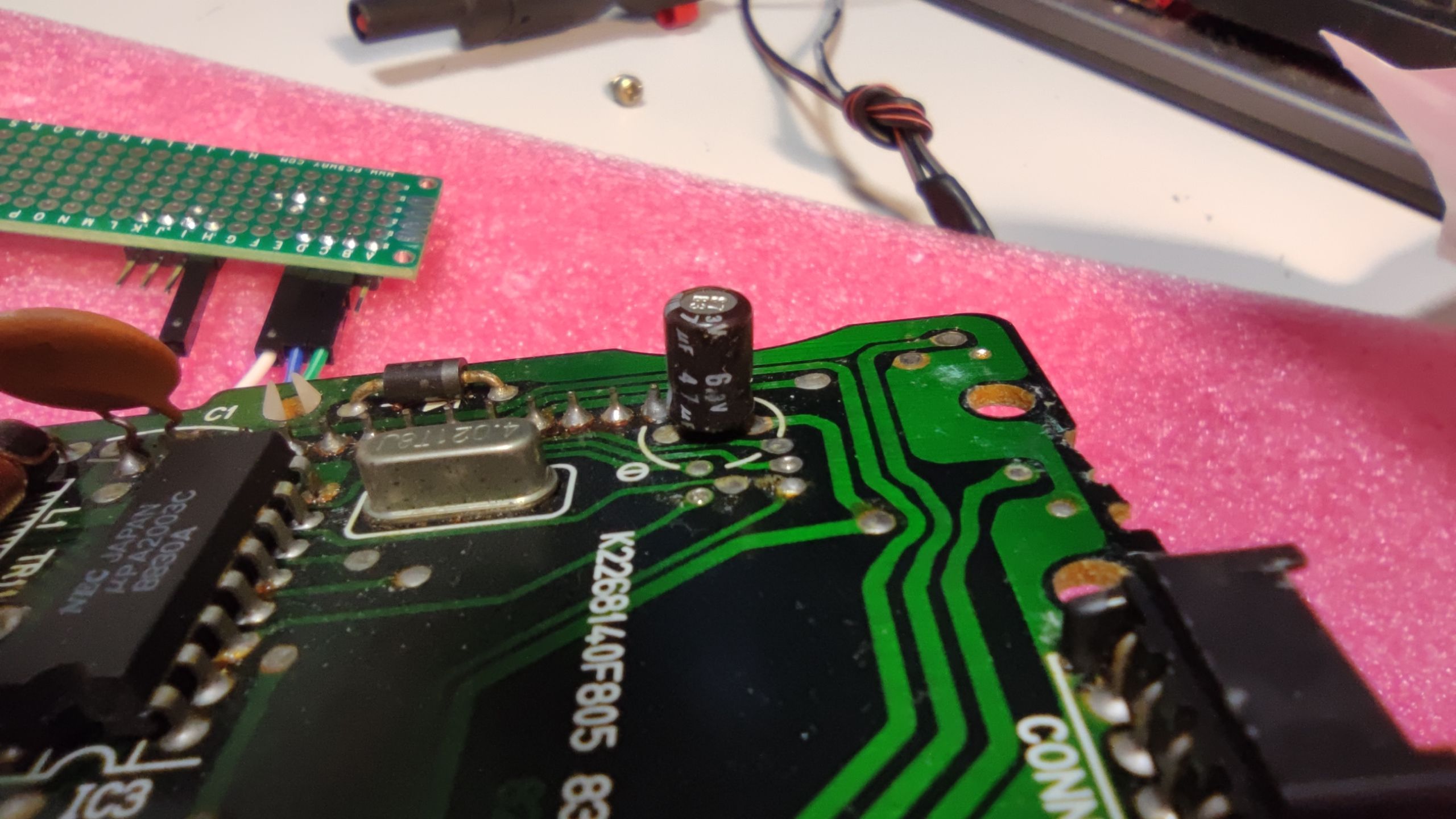
Main board
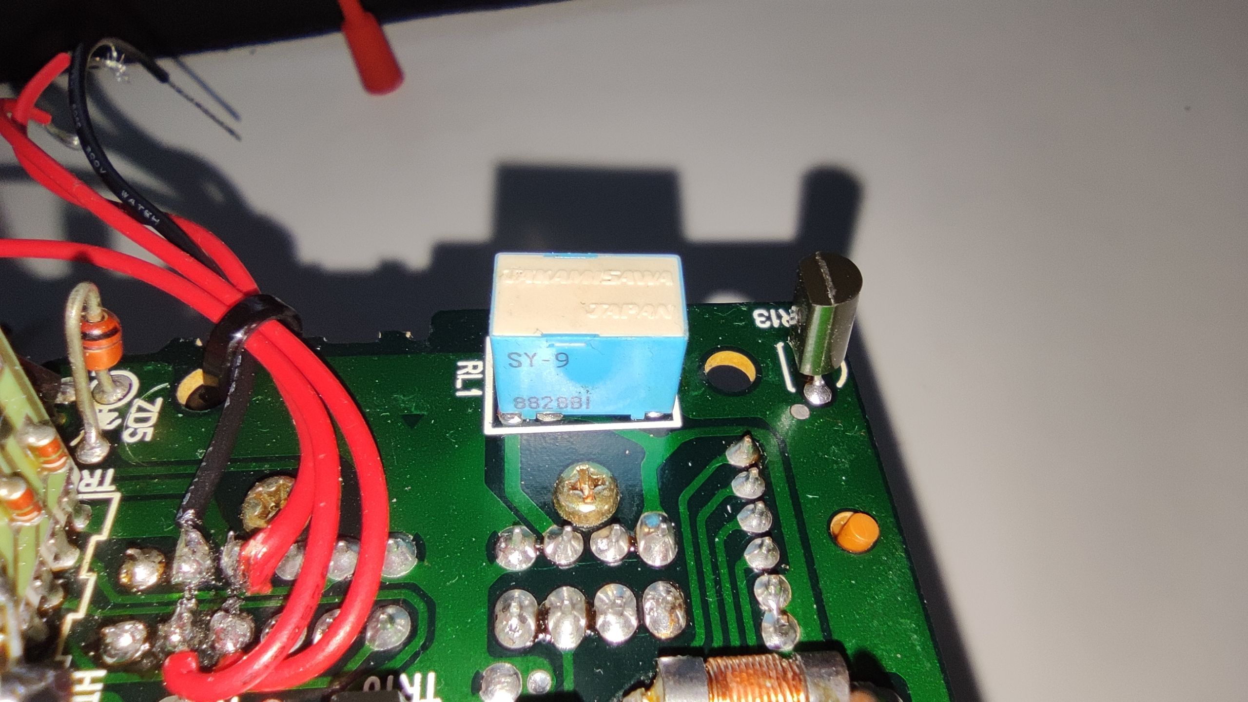
The biggest chip on the main board is Hitachi HD6305Z0 microcontroller. It controls the display board with data/clock/latch signals, +5V_SW power rail enable signal, HUD, and odometer stepper motor.
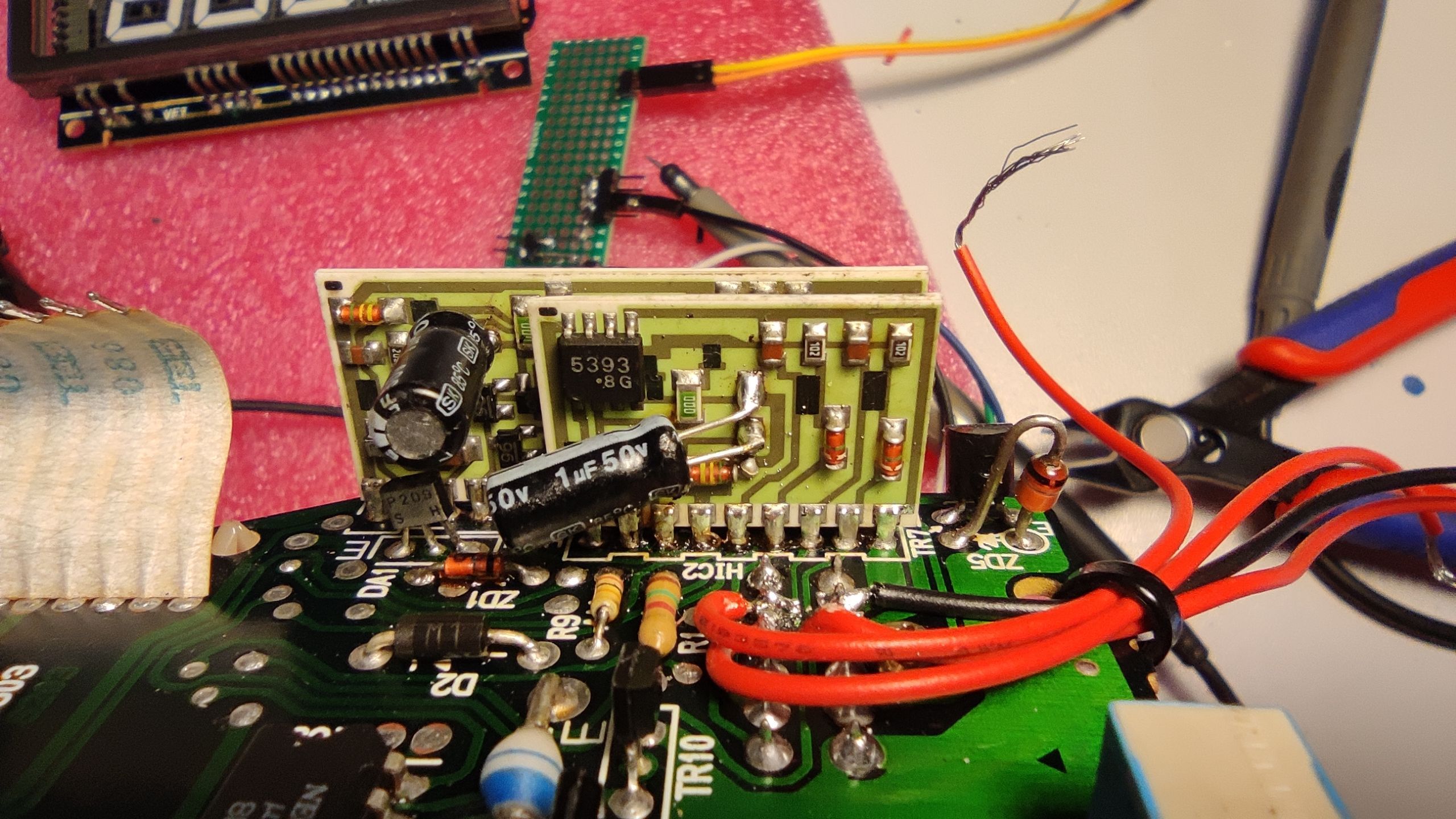
Ceramics board soldered vertically are “Hybrid integrated circuits” HIC1 and HIC2. HIC1 main role is control of microcontroller start-up based on ignition signal and processing of illumination signals. HIC2 is processing speed sensor signal and signals from Head-up display.


Connecting power to main board
Speedometer should power up when power is connected between GND pin 5 and pin 4+10+11 (Ignition and Battery) but be very careful if you are soldering wires directly to PCB. There are traces close to the power pins that goes directly to the IC1. Solder mask on these old PCBs is very thin and dangerous voltage can be connected to the main microcontroller even if the wire that you have soldered to power pin is just touching the trace. This will irreversibly destroy the IC1, don’t ask me how I know this… 🙁

Main boad hybrid IC 1
HIC1 generates reset, NMI and STBY signals for microcontroller and it also handles signal conditioning for ignition and illumination signals.


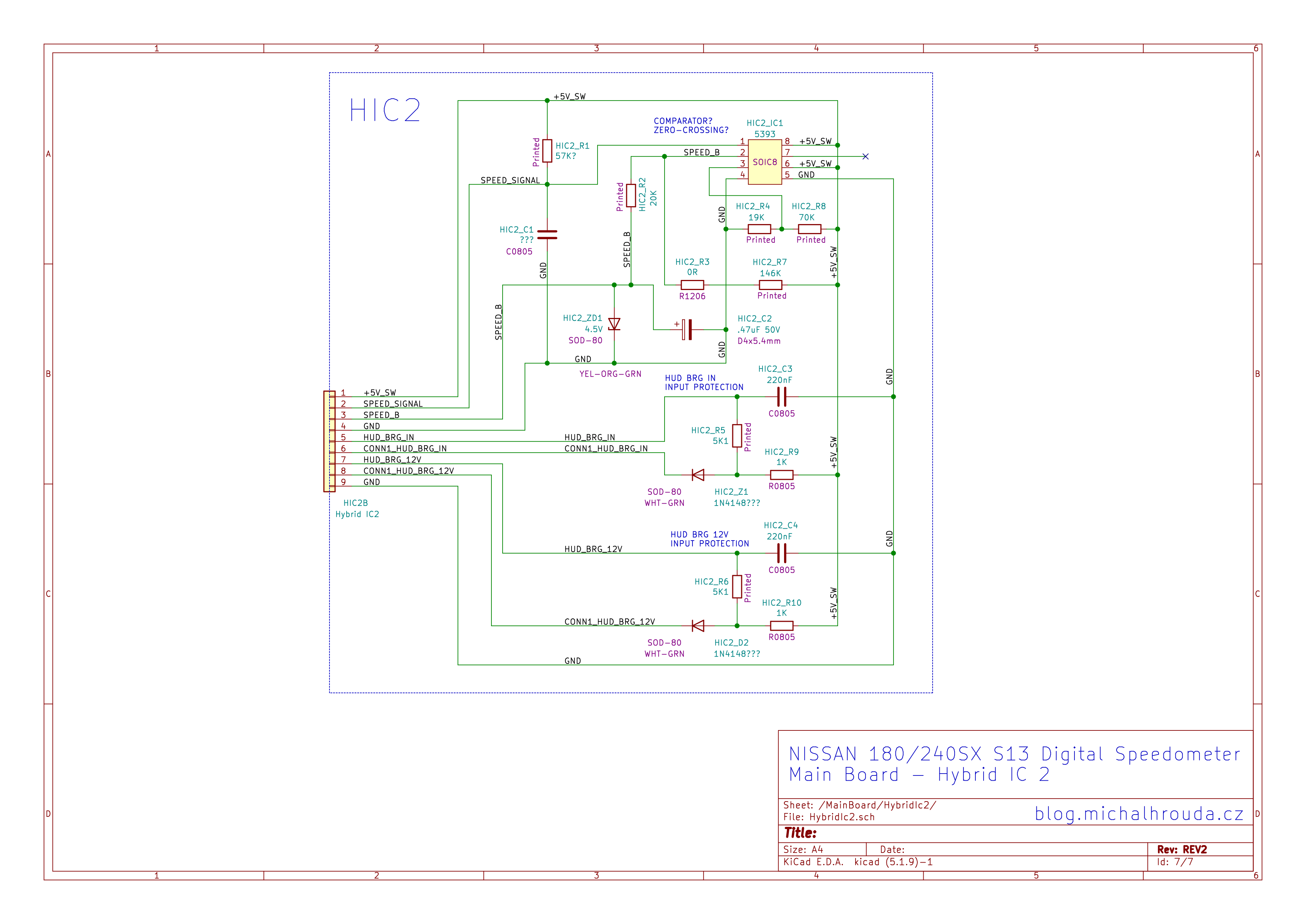
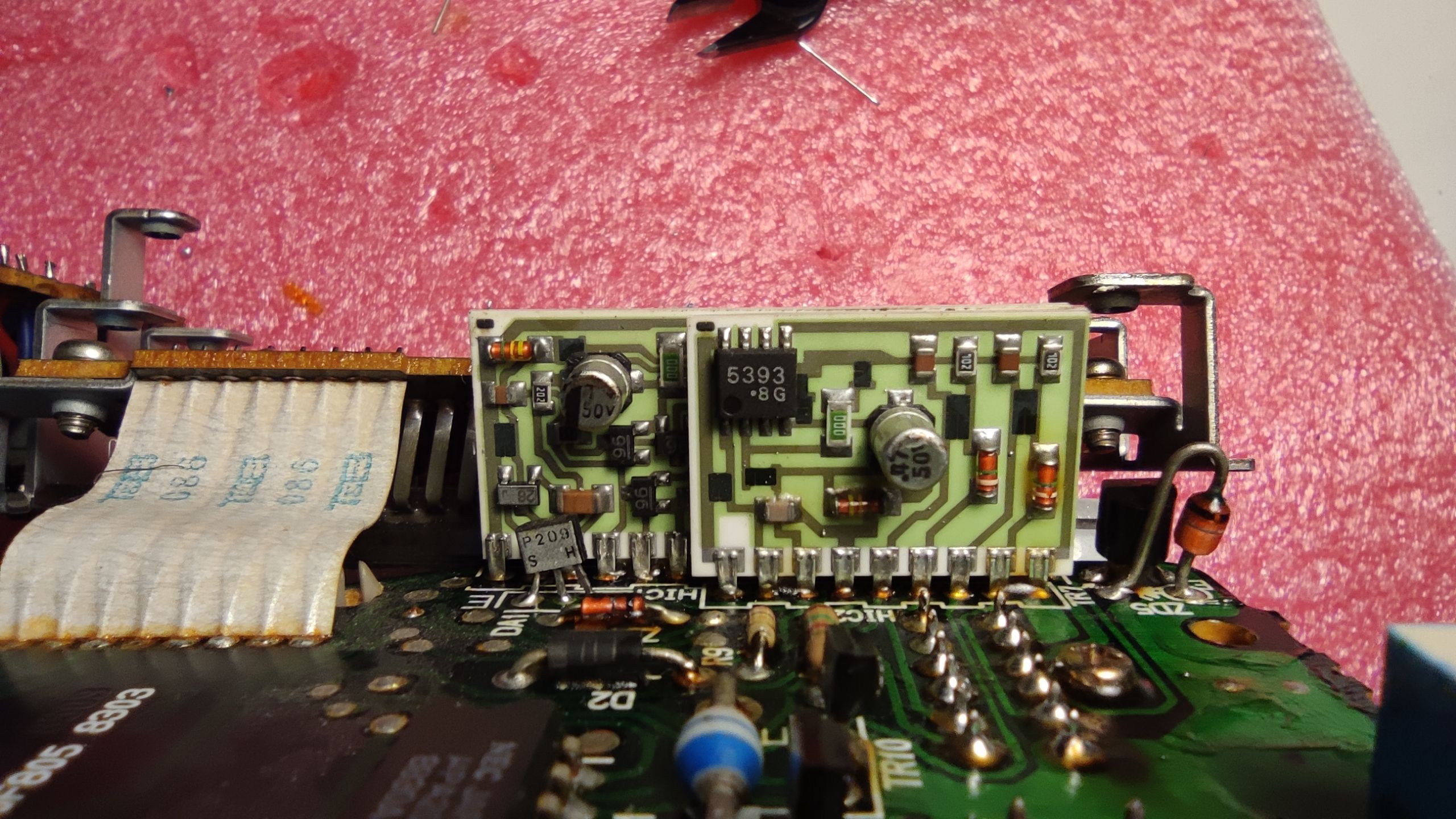
Main boad hybrid IC 2
HIC2 is processing speed sensor signal and signals from Head-up display. I wasn’t able to identify the “5393” chip. My guess is that it is some kind of comparator or zero crossing detector (Zero-crossing is also used on analog speedometer). If your speedometer always shows “0” or speed detection have some issues the problem is most likely on this board. A common issue is the damaged .47uF 50V capacitor.

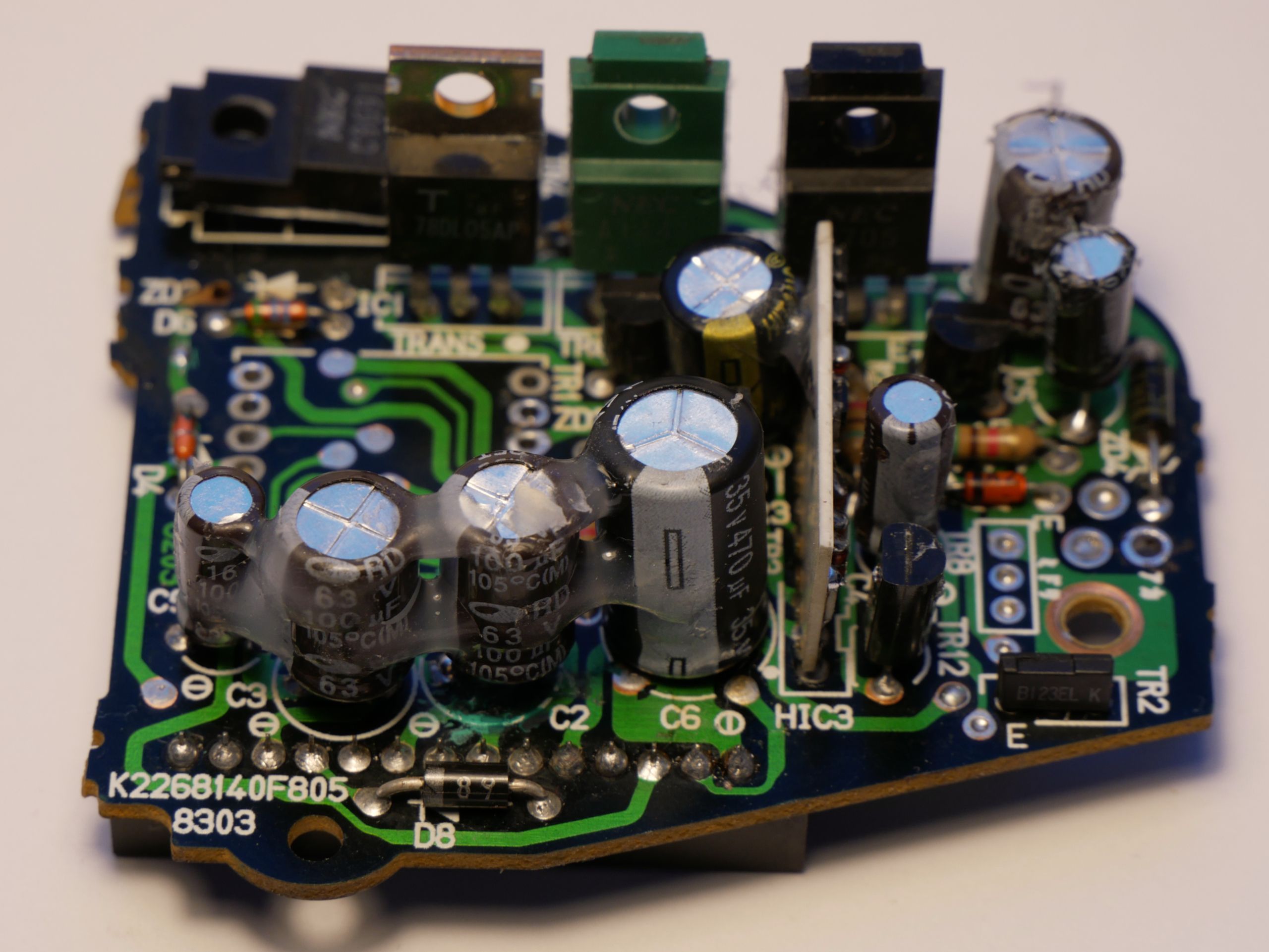
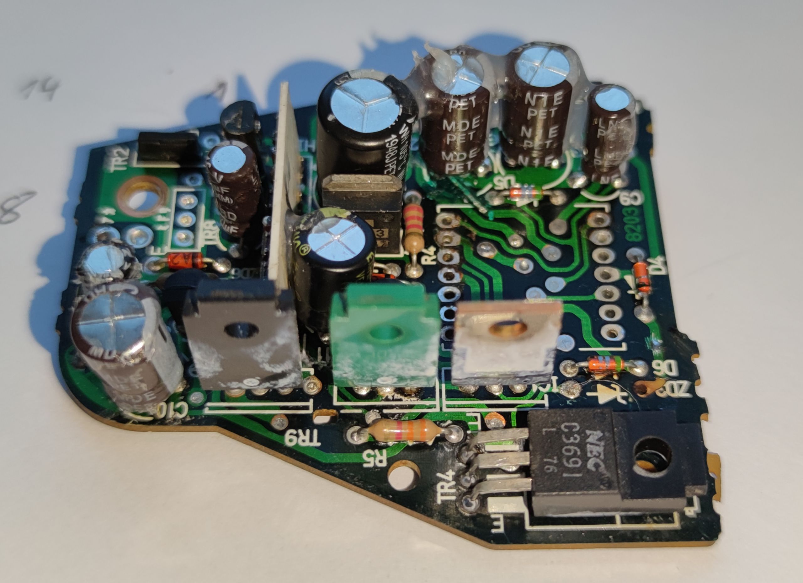
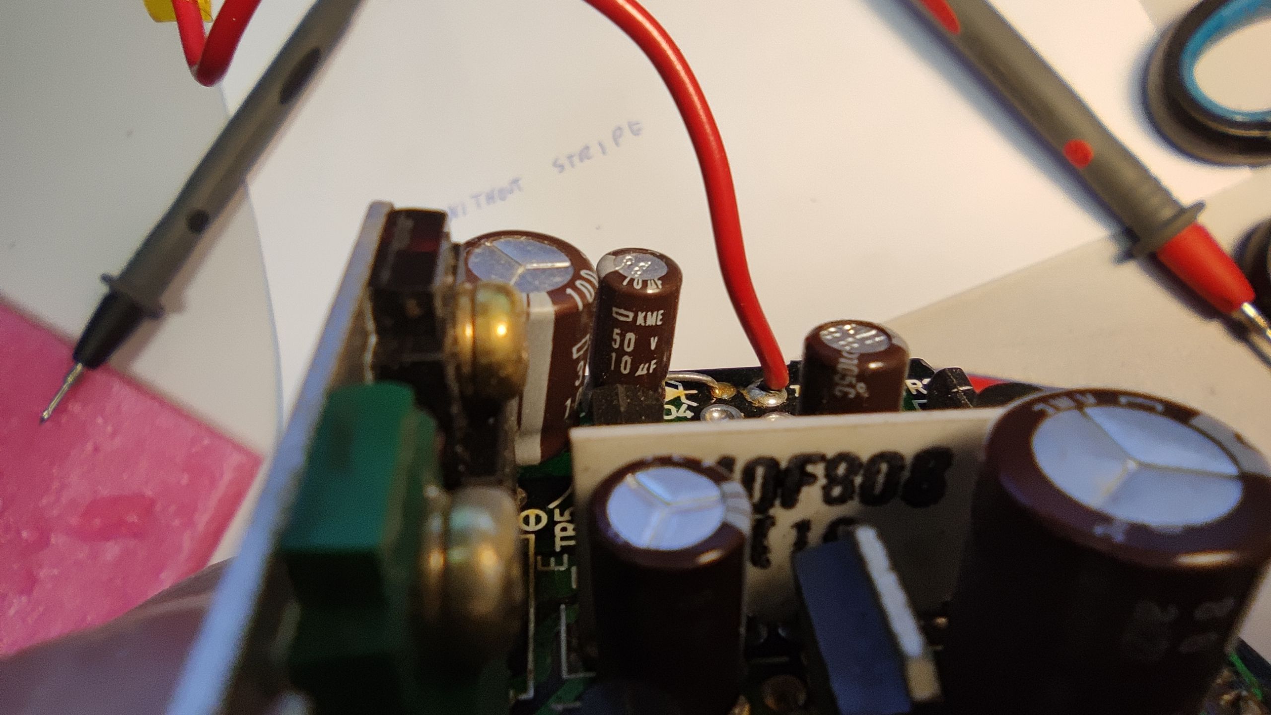
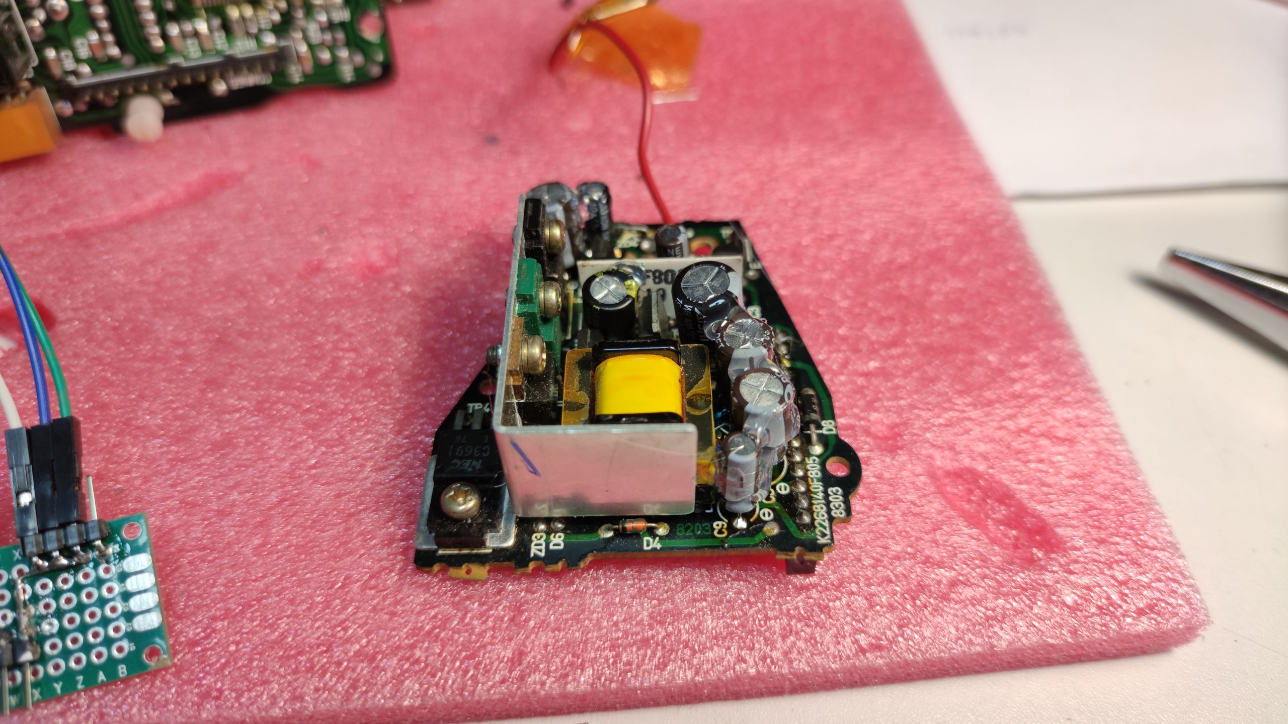
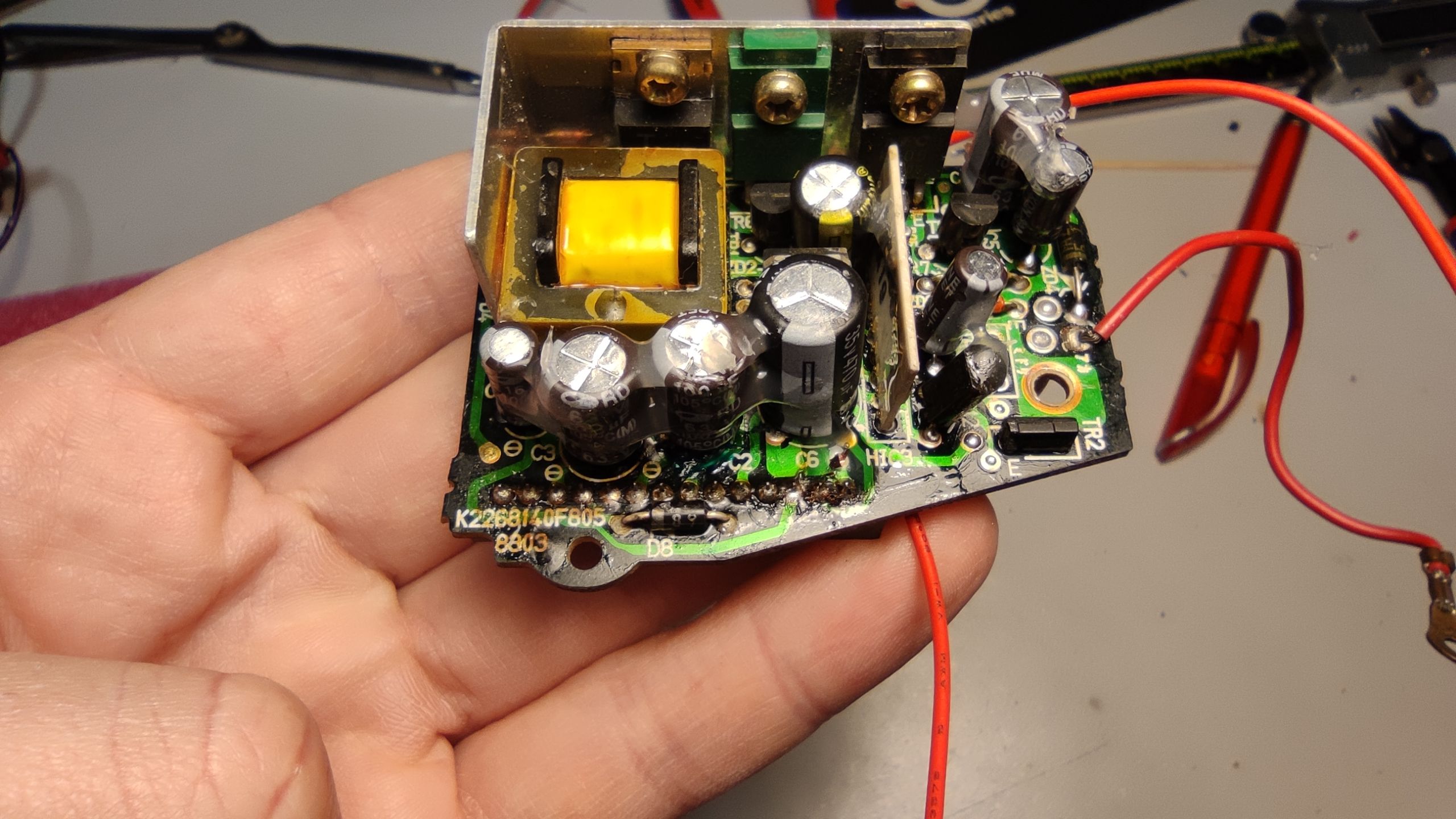
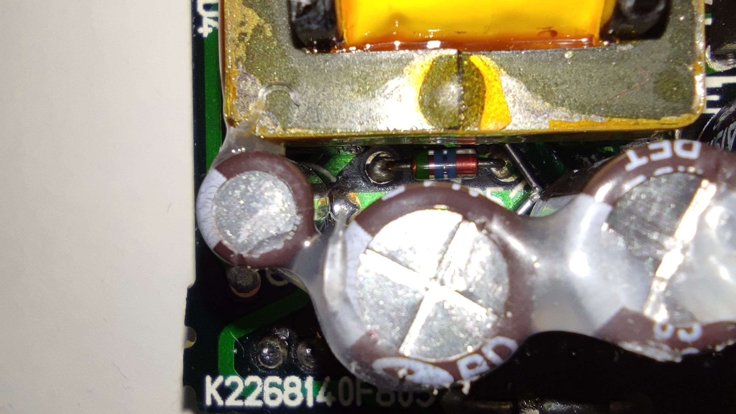
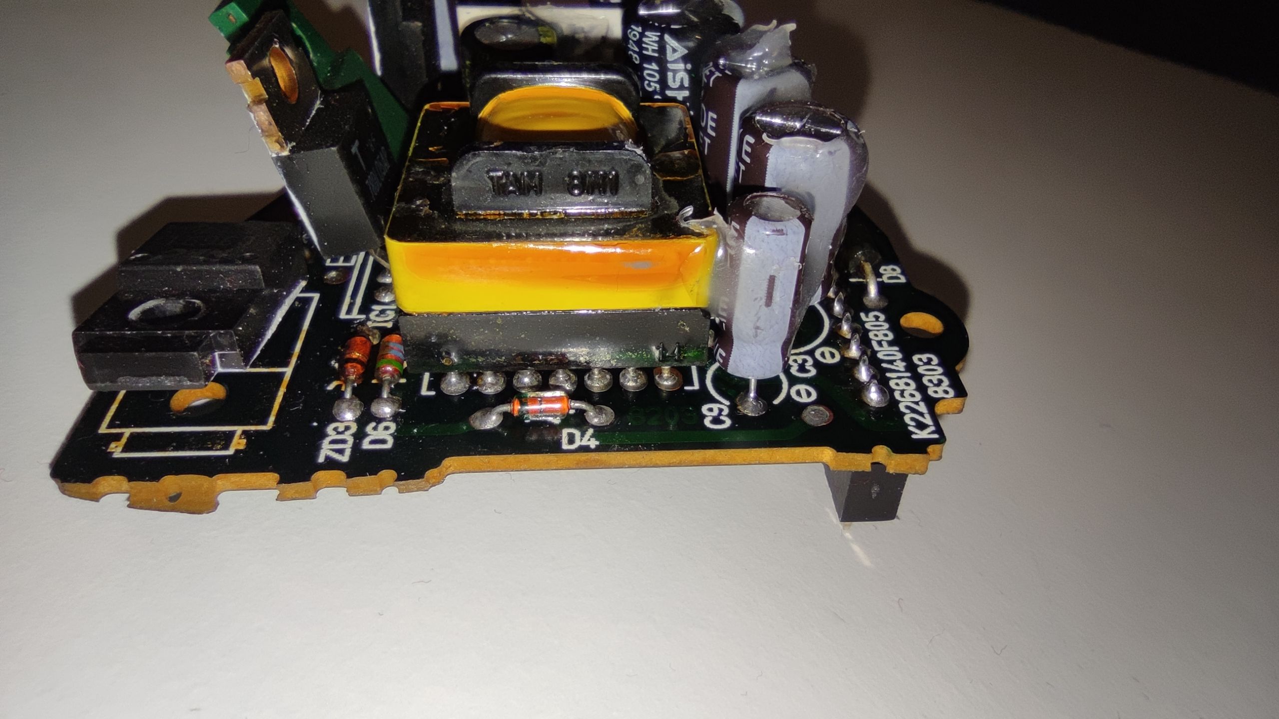
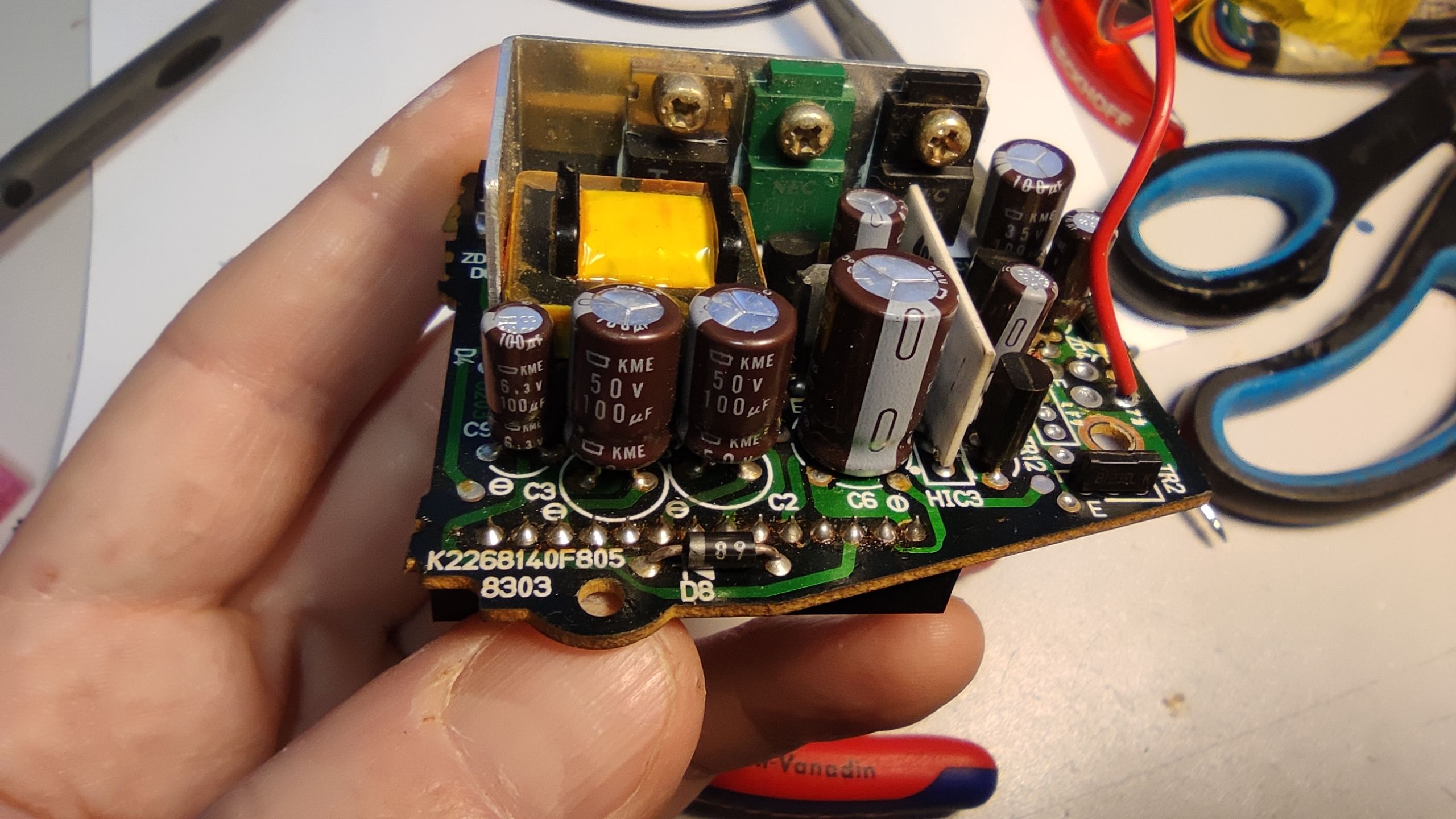
Power supply board
The most time-consuming was the reverse engineering of the power supply. I have no experience with self-oscillating switch power supplies and old-school zener diode driver linear power supplies. I had to redraw the schematics multiple times and I still was not able to understand how the power supply should behave.
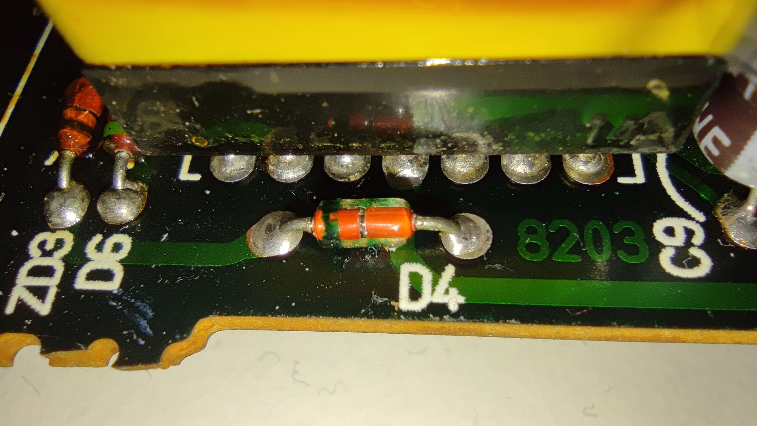
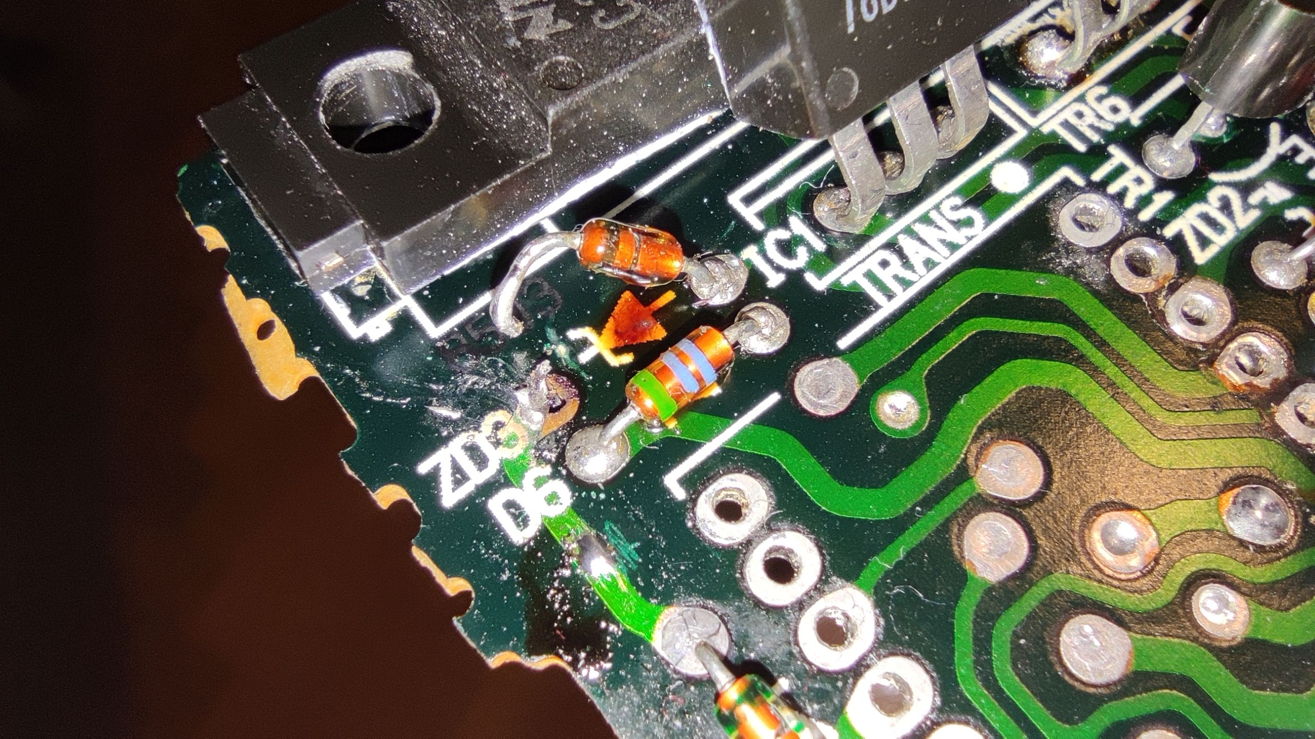
I also found out that the zener diode ZD3 was damaged (0 Ohms in both directions) so I would really appreciate any information about this part. Feel free to write me an email or let me know in the comments.
Update 20220420 More info about ZD3:
“I’ve measured ZD3, and it is a 30V zener diode. I also took a magnifying glass, and saw the numbers 30 and on the other side 2. So probably 30V and 2W.”. Many thanks to Silas Schluchter who sent me this info. I will try to get such zener diode and test it on my board.
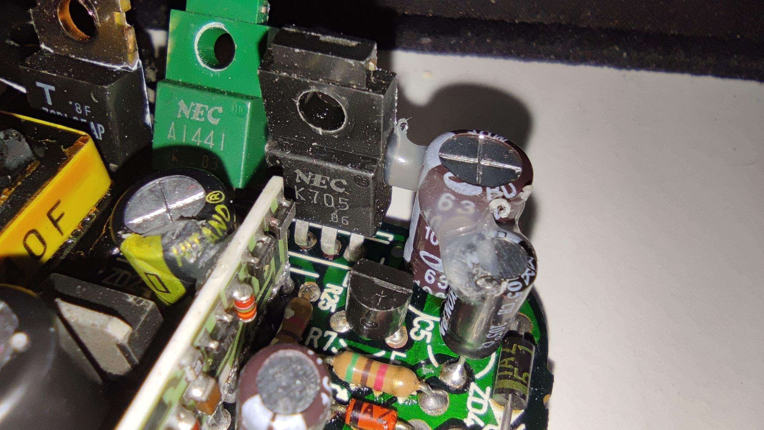
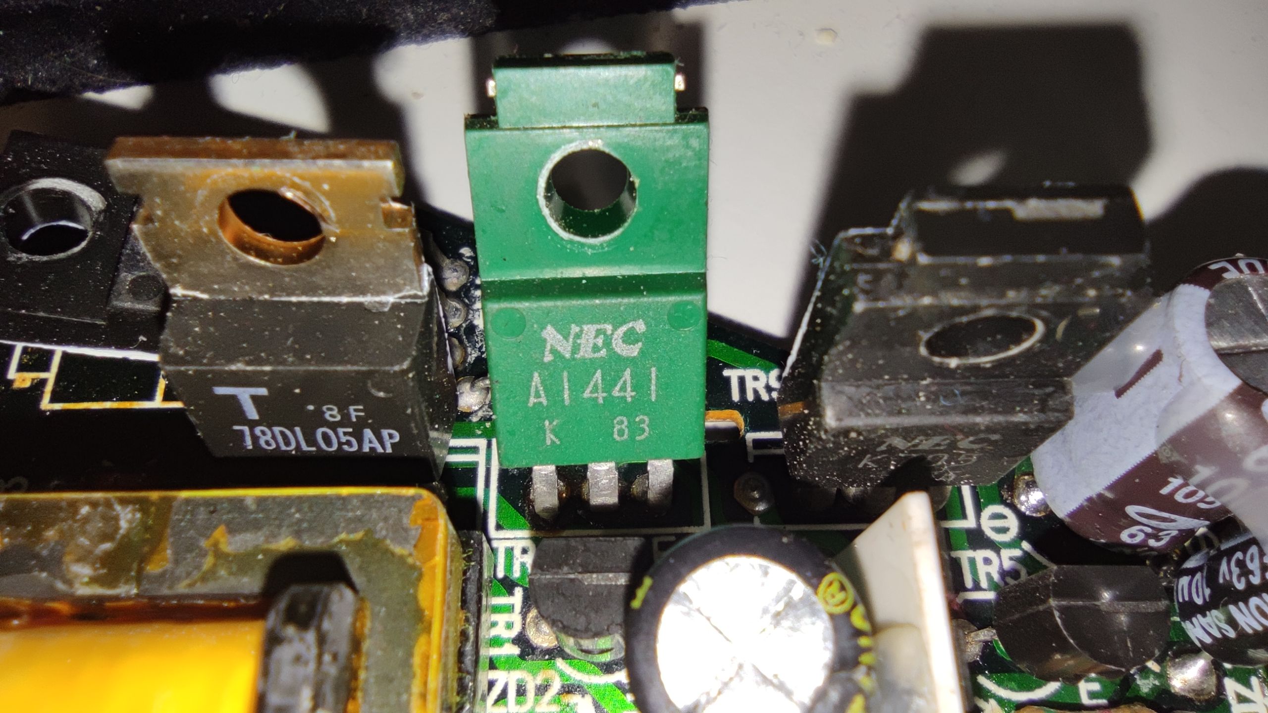
Easy to understand is the +5V section. It uses 78DL05 LDO that powers main board microcontroller when battery is connected. Other circuits that needs +5V are powered by separate power that I’ve called +5_SW. This power rail is enabled only when the ignition is active. Parts that require a higher voltage than +5V are powered from +10V. This includes the display board, HUD relay, and odometer stepper motor.
Sorry for the white balance difference of the photos, I gave up after multiple attempts to unify it.
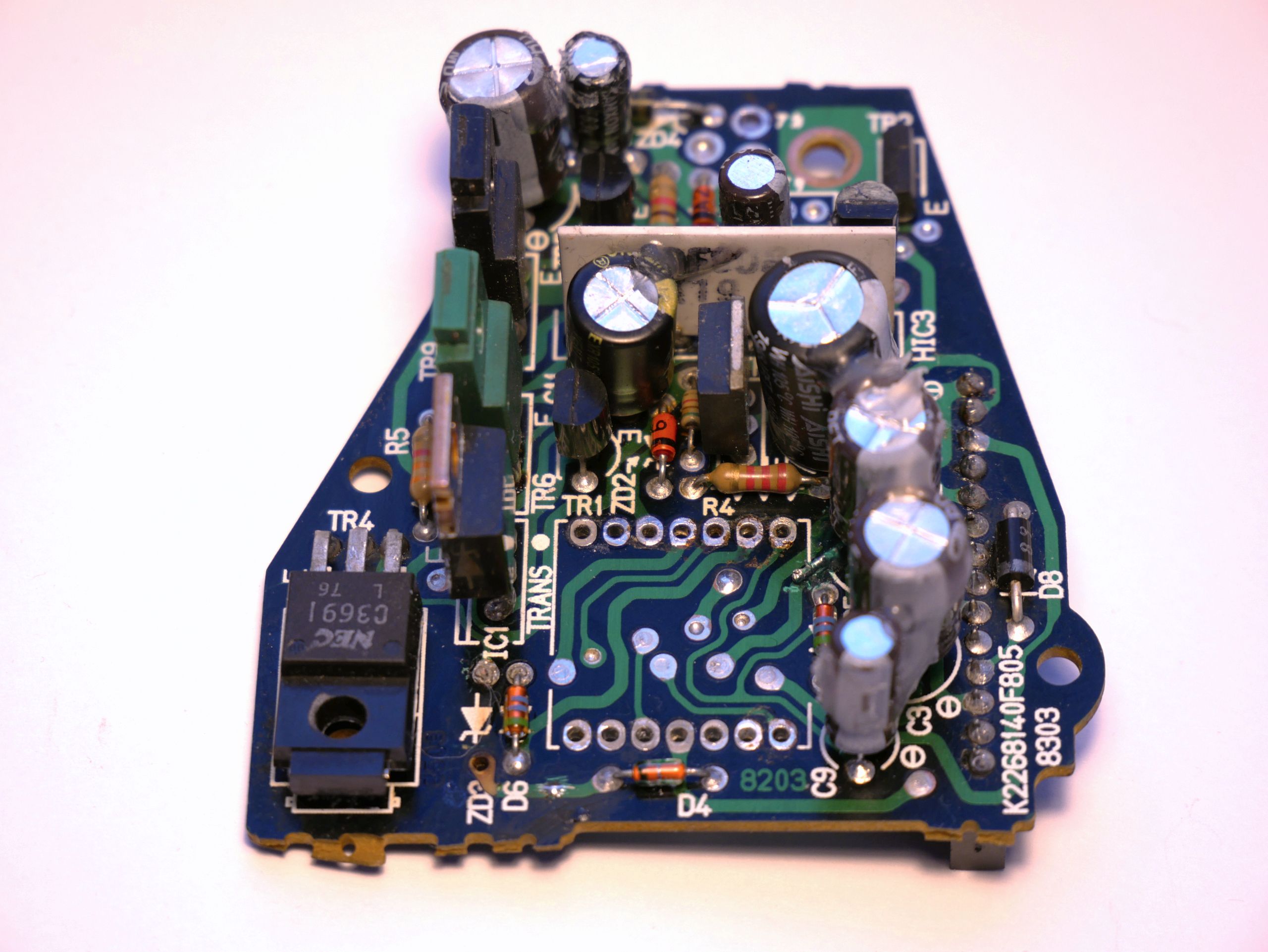


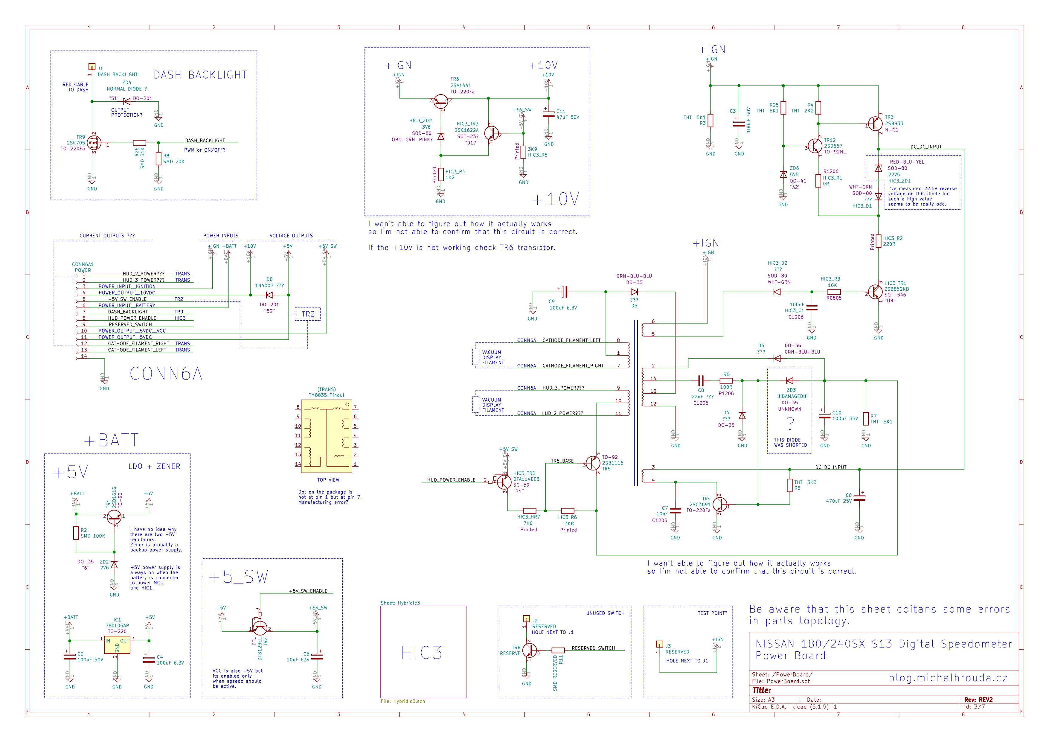
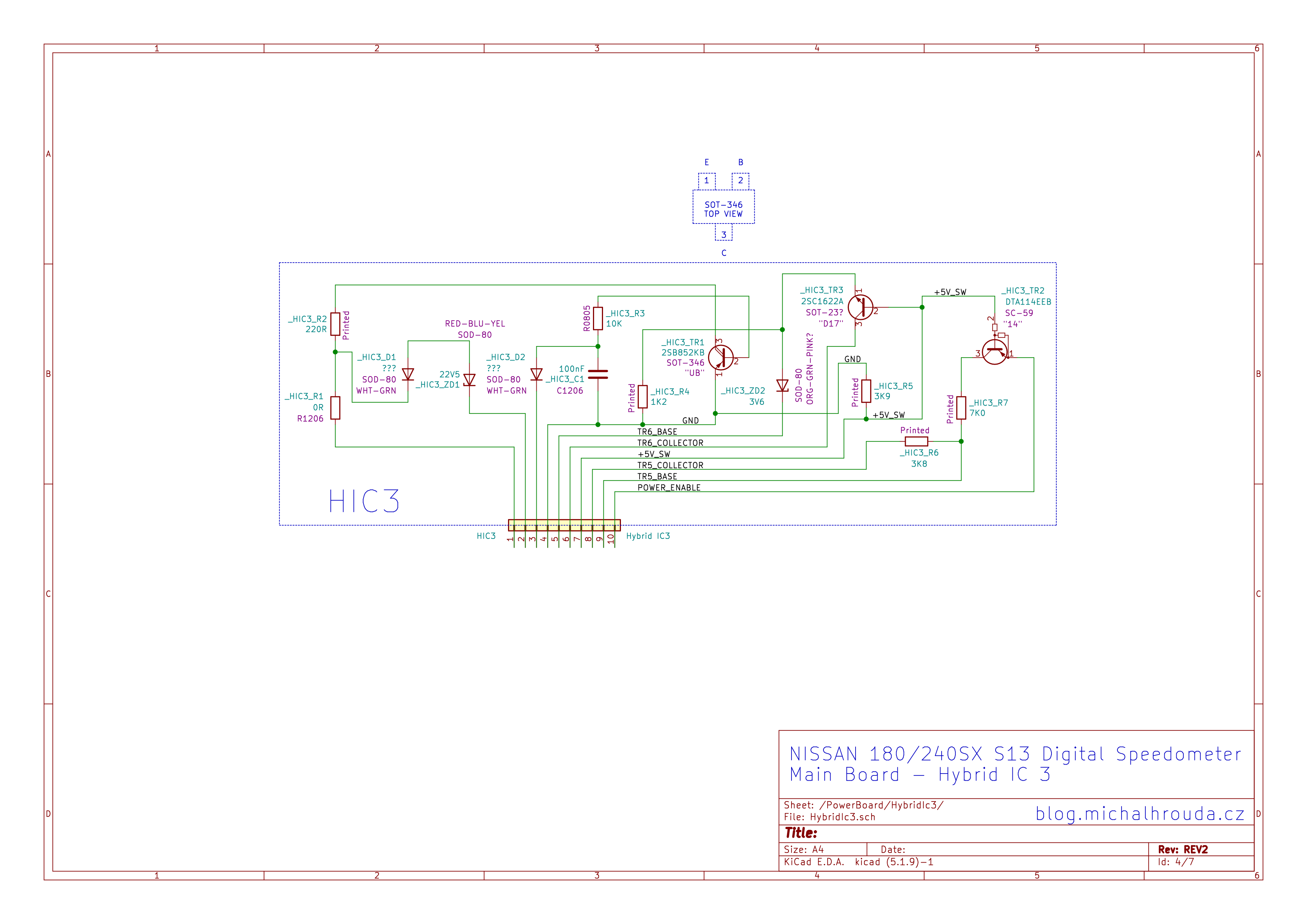
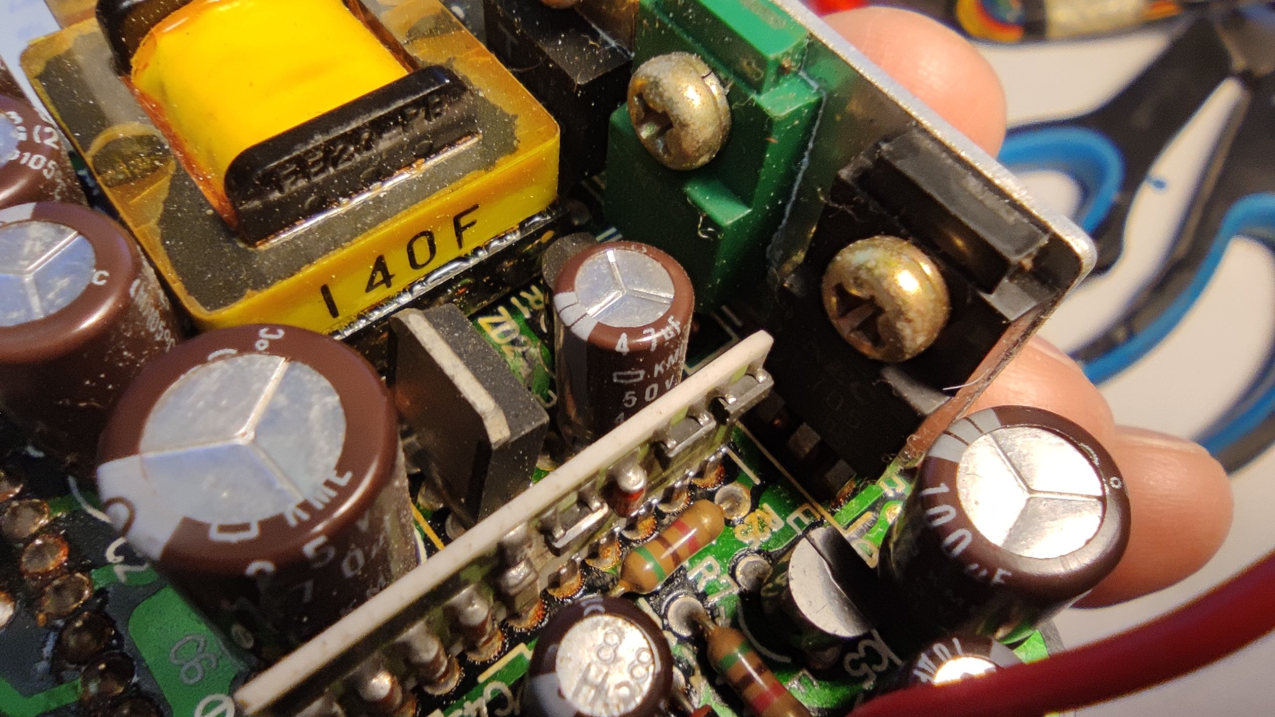
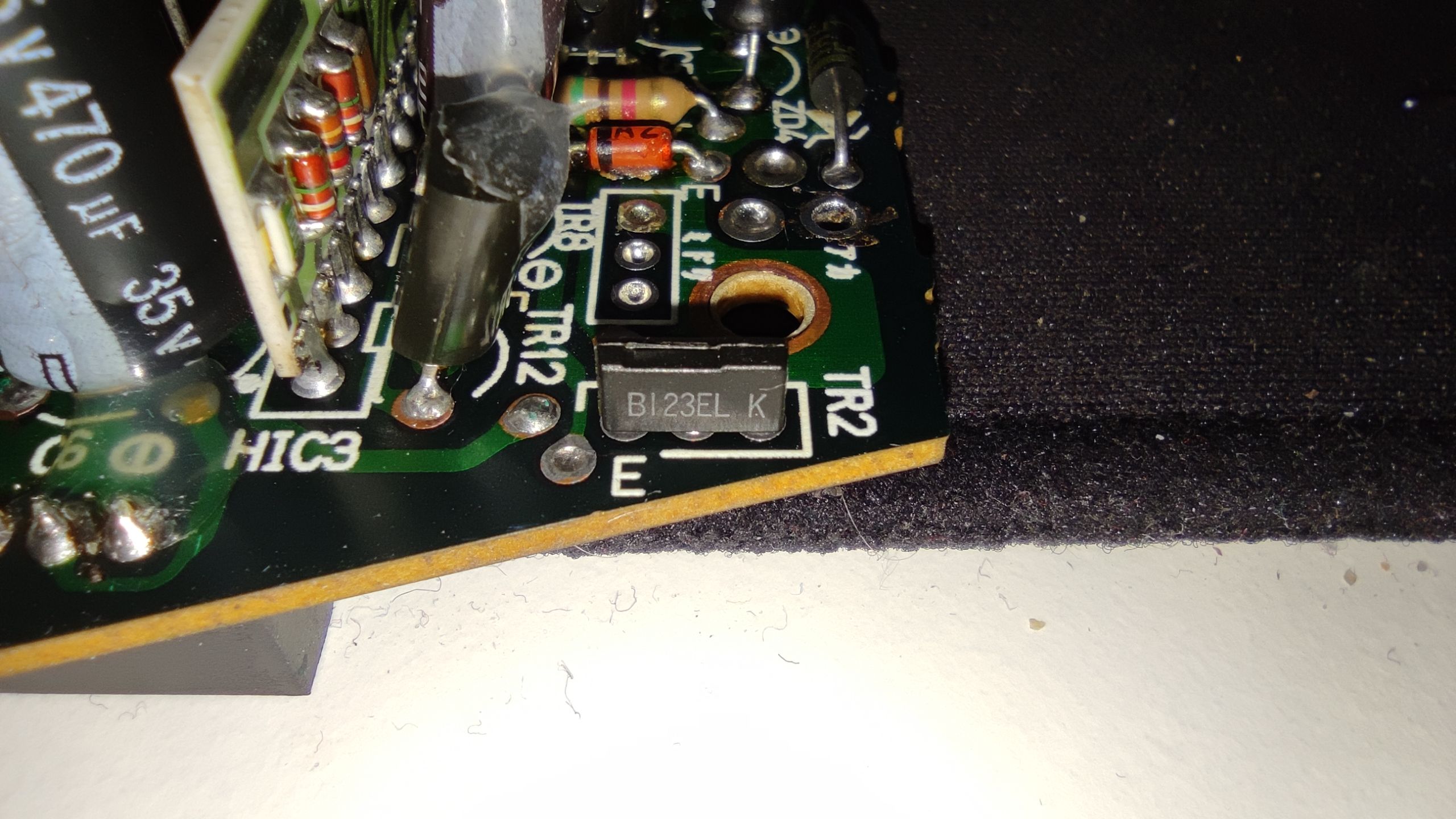
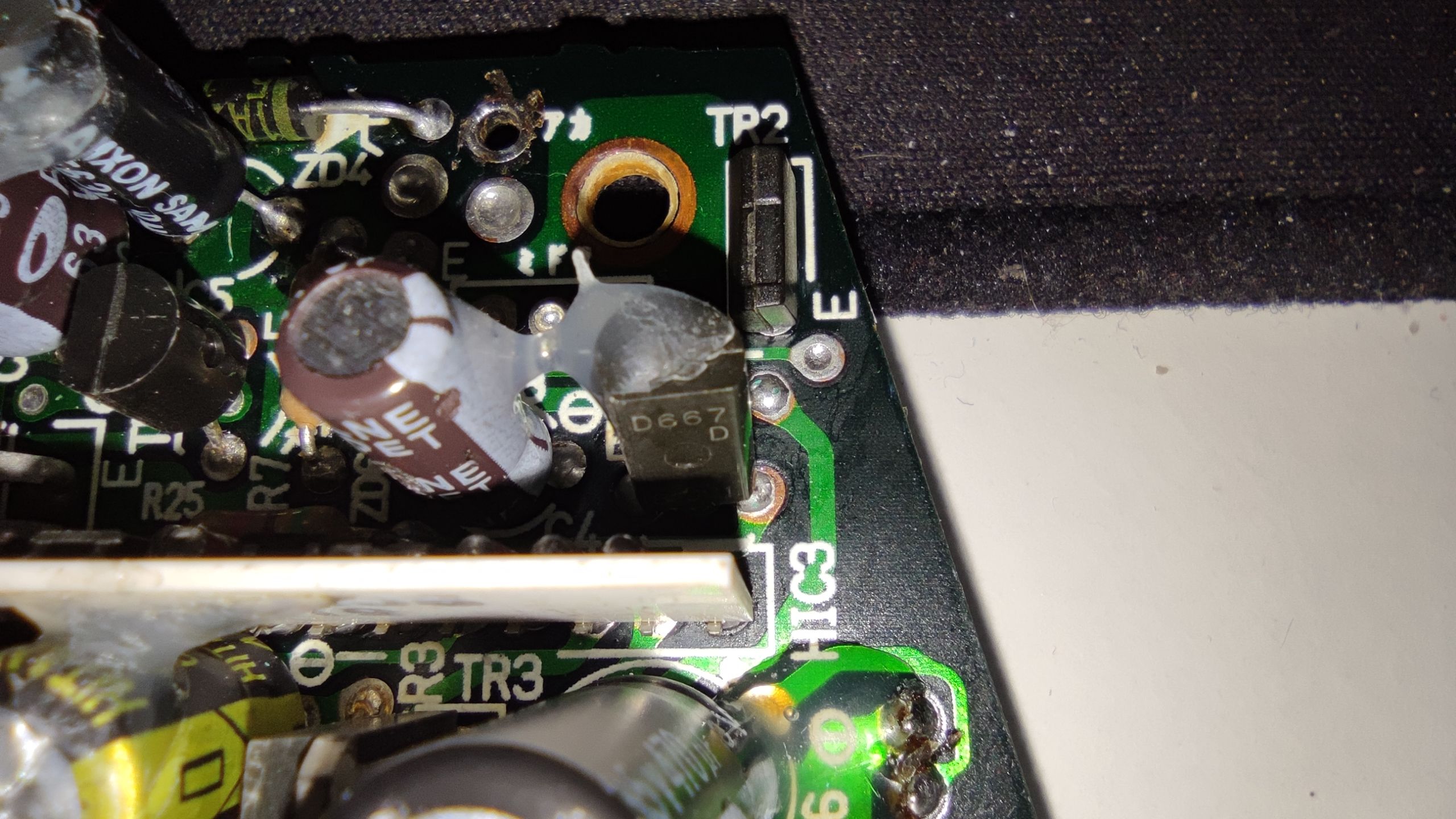
Power supply hybrid IC
HIC3 provides voltage references and switch transistors for the power supply.

Gallery
Main Board


Power Board


Sources and downloads
Forum posts
https://www.nicoclub.com/archives/how-torepair-240sx-digital-speedometer-with-hud.html
https://www.s-chassis.com/forums/general-3/92-240sx-hud-problems-21741/
Installation and repair manuals
http://gary.purplepixie.org/sxoc/Digidash.pdf
Datasheets
| Board | Part Number | Part Name | Download Link | |
| Display | IC101 | PD6323BC | 2SD667.pdf | |
| Main | IC2 | HD6305Z0 | HITACHI-HD63705Z0-HD6305Z0.pdf | |
| Main | IC3 | PA2003C | NEC-PA2003C.pdf | |
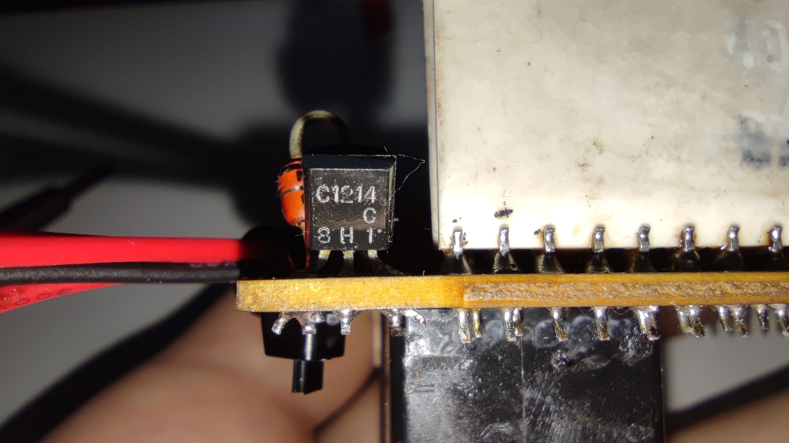
| Main | TR7 | 2SC1214 | 2SC1214.pdf | |
| Main | TR10, TR11 | DTD114EK | DTD114EK.pdf | |
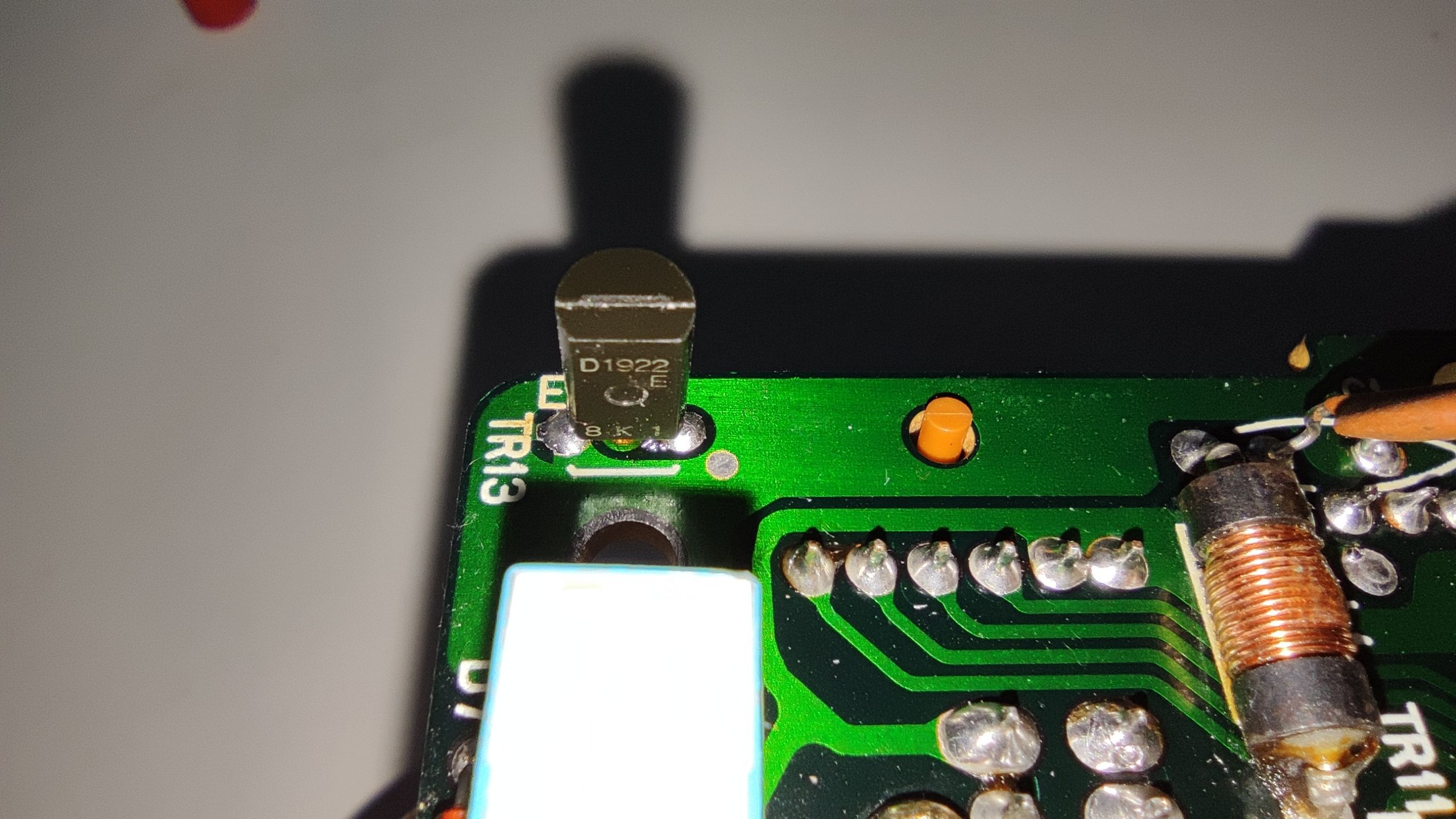
| Main | TR13 | 2SD1922 | 2SD1922.pdf | |
| Main | DA1 | DAP209S | DAP209S.pdf | |
| Main | RL1 | SY-9 | SY9.pdf | |
| HIC1 | TR1 | DTC144ECA | DTC144ECA.pdf | |
| HIC1 | TR2, TR3, TR4 | DTC144TCA | DTC144TCA.pdf | |
| HIC1 | IC1 | 74HC14 | sn74hc14.pdf | |
| Power | IC1 | 78DL05AP | 78DL05S.pdf | |
| Power | TR2 | DTB123EL | DTB123EL.pdf | |
| Power | TR3 | 2SB933 | 2SB933.pdf | |
| Power | TR4 | 2SC3691 | 2SC3691.pdf | |
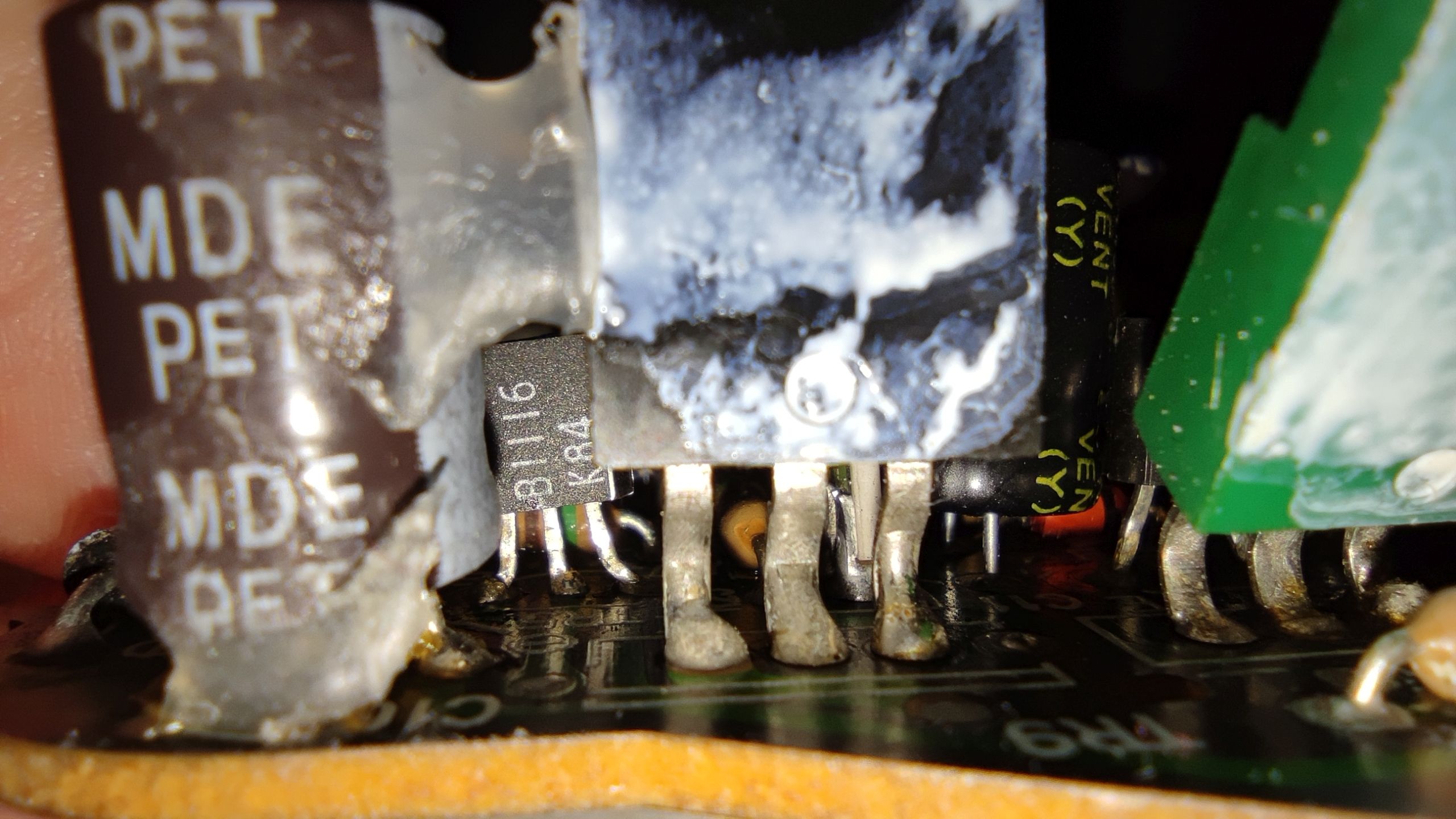
| Power | TR5 | 2SB1116 | 2SB1116.pdf | |
| Power | TR6 | 2SA1441 | 2SA1441.pdf | |
| Power | TR9 | 2SK705 | 2SK705.pdf | |
| Power | TR12 | 2SD667 | 2SD667.pdf | |
| HIC3 | TR1 | 2SB852KB | 2SB852K-B.pdf | |
| HIC3 | TR2 | DTA114EEB | DTA114EEB.pdf | |
| HIC3 | TR3 | 2SC1622A | 2SC1622A.pdf |